Building on from the previous guide, we are going to transition from DMVPN Phase 1 to DMVPN Phase 2. This will bring some important improvements and some considerations.
Lets remind ourselves of the topology:
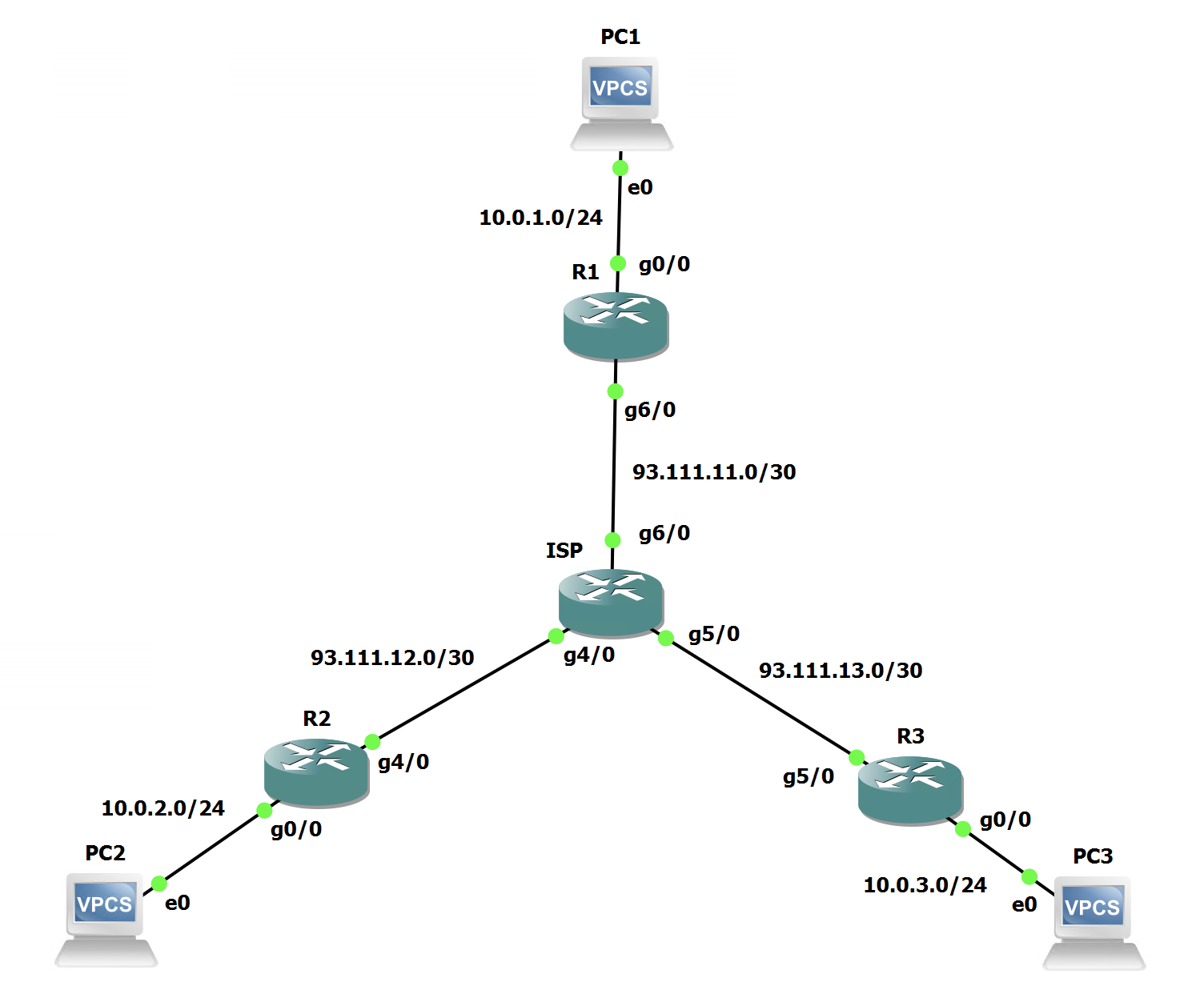
The Hub is still always going to be in the control plane path for the setup of tunnels etc, but we will see the data path adapt.
Hub Configuration - Phase II
Lets look at the changes we need to make on the Hub to move from Phase 1 to 2.
All we need to do, is amend the EIGRP configuration sightly by ensuring that the Hub doesn't change the EIGRP next-hop when its advertising routes to the spokes:
R1(config)#router eigrp Hub
R1(config-router)#address-family ipv4 unicast autonomous-system 65001
R1(config-router-af)#af-interface tunnel 0
R1(config-router-af-interface)#no next-hop-self
You will see the EIGRP relationships gracefully drop and come back up.
Thats it for the Hub!
Spoke Configuration - Phase II
Lets look at the changes we need to make on the Spokes to move from Phase 1 to 2.
On the spokes we need to change the tunnel configuration slightly to make them GRE multipoint, and also remove the static tunnel destination:
R2(config)#int tunnel 0
R2(config-if)#no tunnel destination
R2(config-if)#tunnel mode gre multipoint
The tunnel will go down and should come back up. This needs to be replicated on all spokes.
NHRP Theory - What will happen now?
So, now that the next-hops are not being changed by the Hub. What happens when R2 tries to get to R3's LAN segment, well:
- R2 does a routing lookup for 10.0.3.0/24 and sees the next-hop is R3 (192.168.0.3)
- R2 checks its NHRP Mappings to see if it has a mapping for R3s Tunnel address (192.168.0.3)
- R2 doesn't have a mapping so it sends an NHRP Resolution request to the hub for 192.168.0.3. Requesting R3's NBMA Address.
- The Hub then receives this, knowing its a lookup for R3 (using its own dynamic NHRP mappings). The Hub forwards the Resolution Request to R3.
- R3 receives the request which still contains the Tunnel and NBMA address for R2 and replies directly to R2 with its NBMA Address with a Resolution Reply
If that sounds a bit complex, lets see what happens in a packet capture:
This is the NHRP Resolution Request that was triggered by R2 and sent to the Hub:
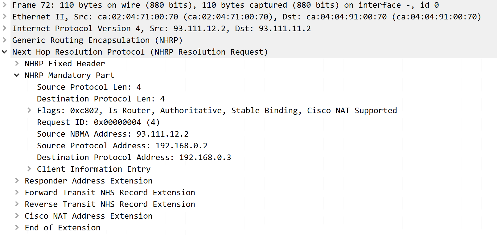
We can see the source IP as 93.111.12.2 which is R2 and the destination IP is 93.111.11.2 which is R1.
The request contains the source NBMA and Protocol (Tunnel) address, and also the Destination Protocol address, which is R3's tunnel address. This is all housed within the 'NHRP Mandatory Part'.
That packet was then processed by the Hub and sent directly to R3:
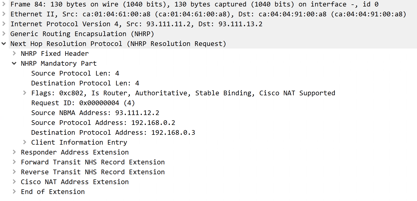
This shows the exact same data under the 'NHRP Mandatory Part'. However as we can see this is being sent from R1 to R3 by the IP header.
R3 then receives the Resolution Request and formulates a Resolution Reply:
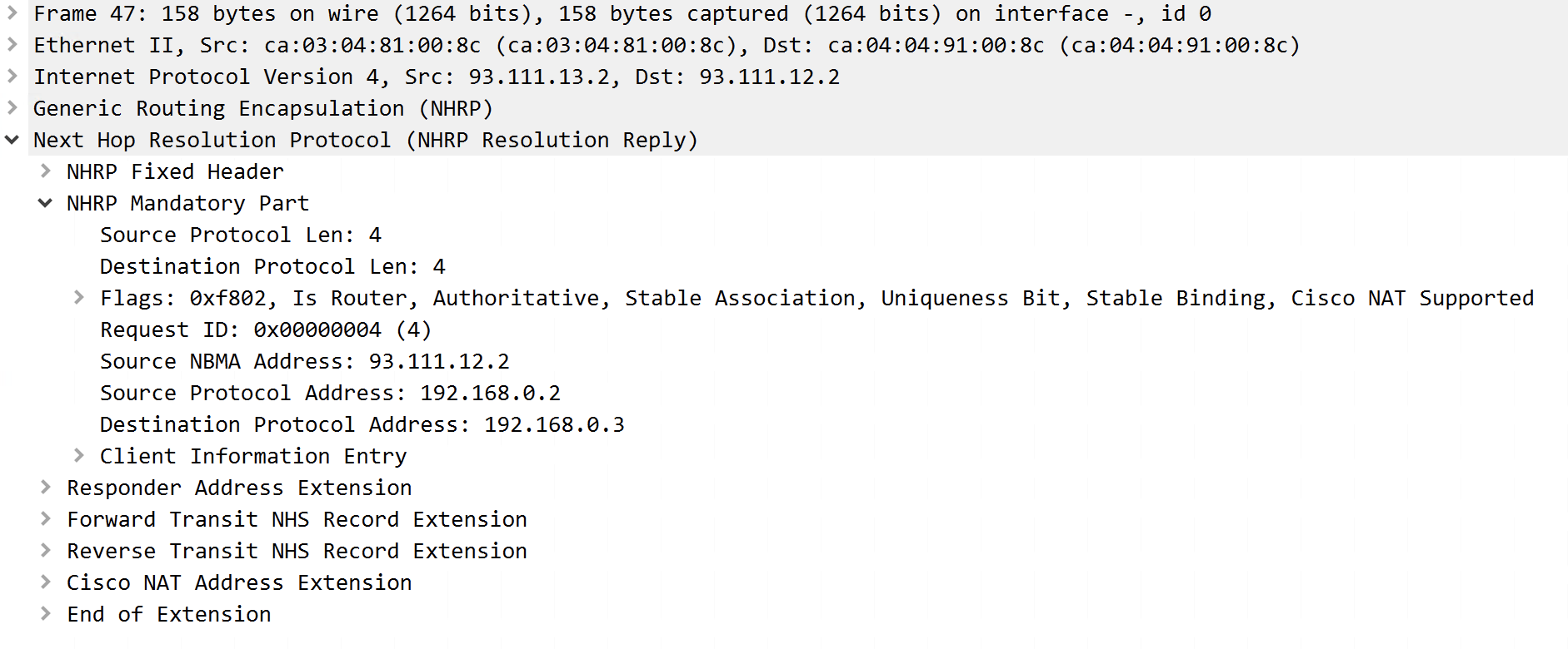
We can see this is sourced from R3 and destined for R2 from the IP header.
It still contains all the same info from the Resolution Request. However, within 'Client Information Entry' there is some additional info:
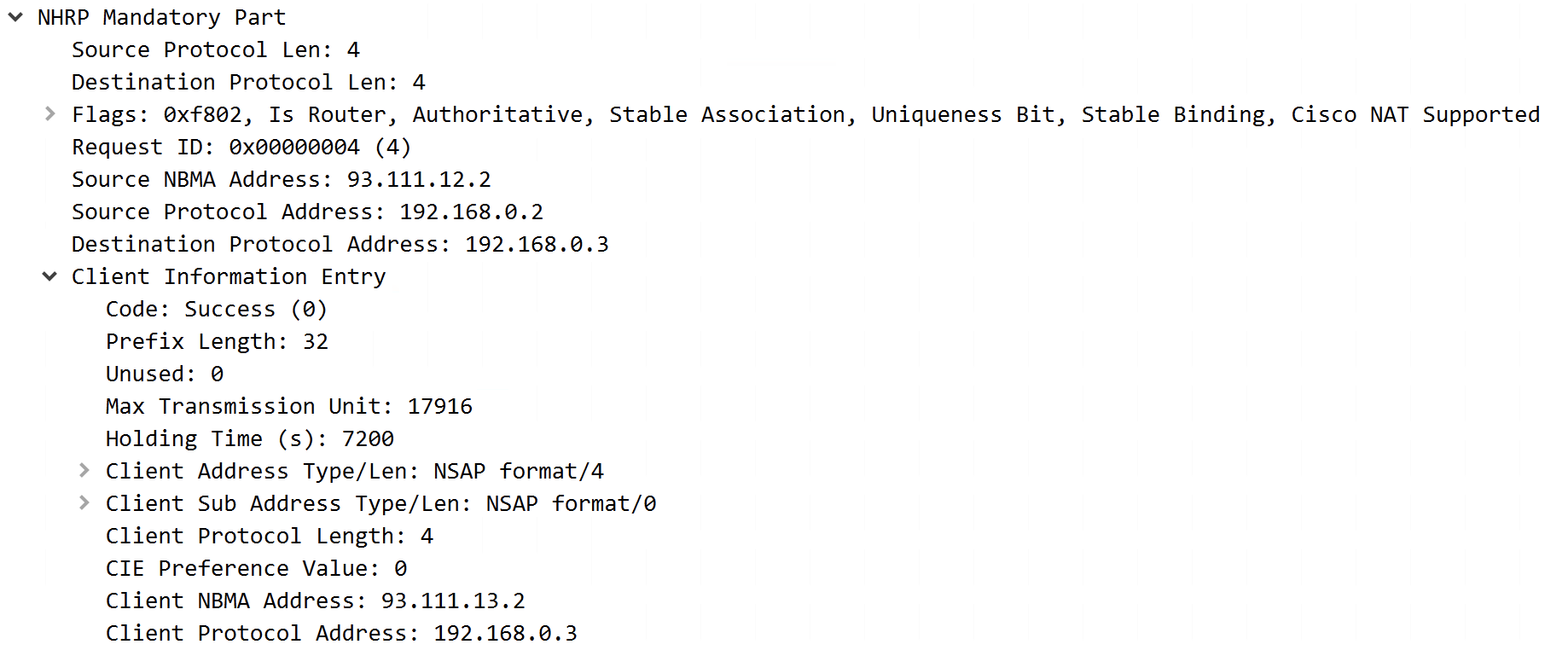
This contains the NBMA Address of R3 and also for verification its Protocol (Tunnel) address.
Once R2 receives this, it adds a dynamic NHRP mapping for R3. Also when the resolution request was digested on R3, it will have added an NHRP mapping for R2. Now the routers can form a dynamic tunnel between each other.
Phase II Verification
Lets look at the data path now:
R2#trace 10.0.3.254 source 10.0.2.254
Type escape sequence to abort.
Tracing the route to 10.0.3.254
VRF info: (vrf in name/id, vrf out name/id)
  1 192.168.0.1 64 msec 28 msec
    192.168.0.3 24 msec
R2#trace 10.0.3.254 source 10.0.2.254
Type escape sequence to abort.
Tracing the route to 10.0.3.254
VRF info: (vrf in name/id, vrf out name/id)
  1 192.168.0.3 40 msec 16 msec 32 msec
This output may be slightly confusing as in the first trace we still see the Hub for the first two packets. This is because while the NHRP Request/Reply is happening, the Hub is used for the first packet to ensure no packet loss occurs. The second trace and 3rd probe on the first trace shows the traffic going straight to R3 without going via the Hub!
We can also see the Dynamic NHRP Mappings on each of the spokes:
R2#show ip nhrp
192.168.0.1/32 via 192.168.0.1
   Tunnel0 created 00:47:15, never expire
   Type: static, Flags: used
   NBMA address: 93.111.11.2
192.168.0.3/32 via 192.168.0.3
   Tunnel0 created 00:02:08, expire 01:57:52
   Type: dynamic, Flags: router used
   NBMA address: 93.111.13.2
R3#show ip nhrp
192.168.0.1/32 via 192.168.0.1
Tunnel0 created 00:45:58, never expire
Type: static, Flags: used
NBMA address: 93.111.11.2
192.168.0.2/32 via 192.168.0.2
Tunnel0 created 00:39:39, expire 01:57:37
Type: dynamic, Flags: router implicit used
NBMA address: 93.111.12.2 We have successfully converted Phase 1 into Phase 2 and also looked under the hood of NHRP to see what its doing when forming the dynamic spoke-to-spoke tunnels.

0 Comments