In this guide, we will setup DMVPN Phase 1. In that we have one central hub, with multiple spokes. Spokes will learn about both Hub and other Spoke prefixes via EIGRP. Spoke to Spoke traffic is permitted, however the Hub is used in the Data Path.
Lets have a look at the Topology:
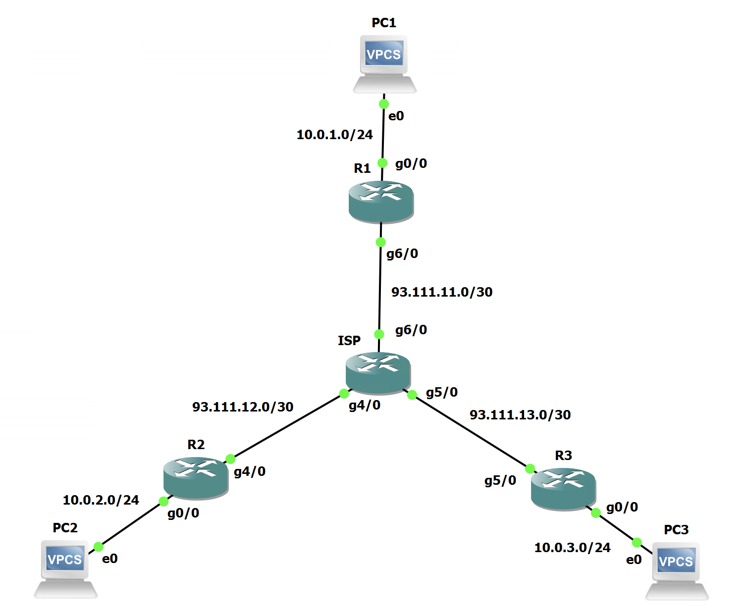
We can see the Public IP addressing on this diagram. This is referred to as the NBMA addressing in DMVPN. Standing for Non-Broadcast Multiple Access. The tunnel addressing will sit on the overlay and will use 192.168.0.0/24.
The LAN segments are also denoted on the document as per the below:
10.0.1.0/24 - Hub R1 Network
10.0.2.0/24 - Spoke R2 Network
10.0.3.0/24 - Spoke R3 Network
Hub Configuration - Phase I
The NBMA and LAN addressing is already present on all routers. Our job is to configure DMVPN Phase I as the overlay to interconnect the sites.
We will begin with the Hub configuration as this is a bit less involved:
interface Tunnel0
 description DMVPN Hub
 ip address 192.168.0.1 255.255.255.0
 no ip redirects
 ip nhrp map multicast dynamic
 ip nhrp network-id 1
 tunnel source GigabitEthernet6/0
 tunnel mode gre multipoint
end
This is the tunnel configuration for the Hub. Lets walk through the commands to ensure we understand them.
no ip redirectsThis command is a best practice for DMVPN
ip nhrp map multicast dynamicThis command tells NHRP (Next Hop Resolution Protocol) to add dynamic spoke registrations to the multicast NHRP mappings. We will see a slightly different version of this command on the spokes.
ip nhrp network-id 1This command sent the NHRP network id. This has to match across the DMVPN topology for the tunnels to form and function. It is a 32 bit number.
tunnel source GigabitEthernet6/0This is a standard GRE tunnel command and sets the source interface for the tunnel. In the case of the Hub, this is the WAN interface G6/0.
tunnel mode gre multipointThis is the final command on the Hub for the base DMVPN setup. It tells the tunnel its mode is gre multipoint. Multipoint is specified as DMVPN is a hub-and-spoke topology and the Hub should expect to form multiple GRE tunnels on this one interface.
Spoke Configuration - Phase I
Now lets move onto the Spoke configuration, this is a little more complex with addresses.
interface Tunnel0
 description DMVPN Spoke
 ip address 192.168.0.2 255.255.255.0
 ip nhrp map 192.168.0.1 93.111.11.2
 ip nhrp map multicast 93.111.11.2
 ip nhrp network-id 1
 ip nhrp nhs 192.168.0.1
 tunnel source GigabitEthernet4/0
 tunnel destination 93.111.11.2
end
This is the tunnel configuration for the Spoke R2. Lets walk through the commands to ensure we understand them.
no ip redirectsThis command is a best practice for DMVPN
ip nhrp map 192.168.0.1 93.111.11.2This command tells NHRP (Next Hop Resolution Protocol) to map the tunnel address of the Hub (192.168.0.1) to the NBMA address of the WAN interface on the Hub. We will see this in NHRP as a static mapping later on.
ip nhrp map multicast 93.111.11.2This command tells NHRP to send all multicast traffic up to the Hubs NBMA address. This allows Dyamic Routing to form over the DMVPN overlay network.
ip nhrp network-id 1This command sent the NHRP network id. This has to match across the DMVPN topology for the tunnels to form and function. It is a 32 bit number.
ip nhrp nhs 192.168.0.1This command sets the NHRP NHS (Next-Hop Server). Note that this uses the Tunnel IP address of the Hub.
tunnel source GigabitEthernet4/0This is a standard GRE tunnel command and sets the source interface for the tunnel. In the case of R2, this is the WAN interface G4/0.
tunnel destination 93.111.11.2This is the final command on the Spoke for the base DMVPN setup. It tells the interface where to form its GRE tunnel to. In this case, its the NBMA address of the Hub.
The above should be replicated on all spoke routers, making sure to substitute IP addressing and interfaces as needed.
Verification - Phase I
Now that we have configured the Hub (R1) and both Spokes (R2 & R3). Lets do some verification before layering EIGRP on top.
Firstly, all the tunnel interfaces should be UP UP:
R1#sh ip int br | inc Interface|Tunnel
Interface              IP-Address      OK? Method Status                Protocol
Tunnel0                192.168.0.1     YES manual up                    up
R2#sh ip int br | inc Interface|Tunnel
Interface IP-Address OK? Method Status Protocol
Tunnel0 192.168.0.2 YES NVRAM up up
R3#sh ip int br | inc Interface|Tunnel
Interface              IP-Address      OK? Method Status                Protocol
Tunnel0                192.168.0.3     YES NVRAM  up                    up
Here we can see all the tunnels are up. This is a great sign as the line status is up too. This shows the tunnels are functioning.
Now, lets check that both spokes have static entries for the Hub in NHRP:
R2#show ip nhrp
192.168.0.1/32 via 192.168.0.1
   Tunnel0 created 00:09:11, never expire
   Type: static, Flags:
   NBMA address: 93.111.11.2
R3#show ip nhrp
192.168.0.1/32 via 192.168.0.1
Tunnel0 created 00:04:33, never expire
Type: static, Flags:
NBMA address: 93.111.11.2 So, we can see that both Spokes have NHRP mappings for 192.168.0.1 which is the Hub, this is mapped to the NBMA address of 93.111.11.2 and its set to never expire and the type is static, great!
Finally, lets check that the Hub has dynamic mappings for both Spokes using the same command:
R1#show ip nhrp
192.168.0.2/32 via 192.168.0.2
   Tunnel0 created 00:01:09, expire 01:58:50
   Type: dynamic, Flags: unique registered used
   NBMA address: 93.111.12.2
192.168.0.3/32 via 192.168.0.3
   Tunnel0 created 00:00:23, expire 01:59:36
   Type: dynamic, Flags: unique registered used
   NBMA address: 93.111.13.2
This shows both R2 and R3 as registered with dynamic addresses. We see both their tunnel address and NBMA WAN addresses.
All looks good with the DMVPN setup for now. We can begin layering EIGRP on top of it.
EIGRP Configuration - Phase I
In this guide I am going to use EIGRP Named Mode.
Lets look at the configuration for the hub:
router eigrp Hub
 !
 address-family ipv4 unicast autonomous-system 6500
  !
  af-interface default
   passive-interface
  exit-af-interface
  !
  af-interface Tunnel0
   no passive-interface
   no split-horizon
  exit-af-interface
  !
  topology base
  exit-af-topology
  network 10.0.1.0 0.0.0.255
  network 192.168.0.0
 exit-address-family
This configuration sets all interfaces except the DMVPN tunnel as passive and then brings the Tunnel network and LAN segment into EIGRP using ASN 65001. There is some special configuration under the Tunnel interface. It disables the split-horizon feature in EIGRP where it will not advertise a route back out the interface it was received. We need this turned off in EIGRP as routes will be advertised to and from the Tunnel interface.
Now lets look at the spoke EIGRP configuration, though its much the same:
router eigrp Spoke
 !
 address-family ipv4 unicast autonomous-system 65001
  !
  af-interface default
   passive-interface
  exit-af-interface
  !
  af-interface Tunnel0
   no passive-interface
  exit-af-interface
  !
  topology base
  exit-af-topology
  network 10.0.0.0 0.0.255.255
  network 192.168.0.0
 exit-address-family
Same goes here with the passive interfaces and both LAN segment and Tunnel addressing being brought into EIGRP.
We can see on the Hub that it has two EIGRP neighborships:
R1#show eigrp address-family ipv4 neighbors
EIGRP-IPv4 VR(Hub) Address-Family Neighbors for AS(65001)
H   Address                 Interface              Hold Uptime   SRTT   RTO  Q  Seq
                                                   (sec)         (ms)       Cnt Num
1   192.168.0.3             Tu0                      14 00:00:20   31  1470  0  3
0   192.168.0.2             Tu0                      10 00:02:06   71  1470  0  4
We can also see the prefixes the Spokes have advertised in the Topology table:
R1#show eigrp address-family ipv4 topology
EIGRP-IPv4 VR(Hub) Topology Table for AS(65001)/ID(192.168.0.1)
Codes: P - Passive, A - Active, U - Update, Q - Query, R - Reply,
       r - reply Status, s - sia Status

P 10.0.3.0/24, 1 successors, FD is 9831055360
        via 192.168.0.3 (9831055360/1310720), Tunnel0
P 10.0.1.0/24, 1 successors, FD is 1310720
        via Connected, GigabitEthernet0/0
P 192.168.0.0/24, 1 successors, FD is 9830400000
        via Connected, Tunnel0
P 10.0.2.0/24, 1 successors, FD is 9831055360
        via 192.168.0.2 (9831055360/1310720), Tunnel0
We can see the spoke routers as the feasible successors for their networks respectively.
Now lets check what we can see on Spoke 1 in the routing table:
R2#show ip route | beg Gateway
Gateway of last resort is 93.111.12.1 to network 0.0.0.0

S*    0.0.0.0/0 [1/0] via 93.111.12.1
      10.0.0.0/8 is variably subnetted, 4 subnets, 2 masks
D        10.0.1.0/24 [90/76805120] via 192.168.0.1, 00:04:10, Tunnel0
C        10.0.2.0/24 is directly connected, GigabitEthernet0/0
L        10.0.2.254/32 is directly connected, GigabitEthernet0/0
D        10.0.3.0/24 [90/102405120] via 192.168.0.1, 00:02:24, Tunnel0
      93.0.0.0/8 is variably subnetted, 2 subnets, 2 masks
C        93.111.12.0/30 is directly connected, GigabitEthernet4/0
L        93.111.12.2/32 is directly connected, GigabitEthernet4/0
      192.168.0.0/24 is variably subnetted, 2 subnets, 2 masks
C        192.168.0.0/24 is directly connected, Tunnel0
L        192.168.0.2/32 is directly connected, Tunnel0
We can see two EIGRP routes. One is the Hub subnet and the other is from the other spoke. However both have a next hop of the Hub. This is how Phase 1 is intended to function. All traffic is hair-pinned by the Hub. We can confirm this with a traceroute from R2 to R3:
R2#trace 10.0.3.1
Type escape sequence to abort.
Tracing the route to 10.0.3.1
VRF info: (vrf in name/id, vrf out name/id)
  1 192.168.0.1 40 msec 40 msec 40 msec
  2 192.168.0.3 84 msec 72 msec 80 msec
  3 10.0.3.1 112 msec 64 msec 52 msec
This shows the path from R2 to R3's LAN segment. This goes up to the Hub (192.168.0.1) before being pushed down to R3.
This is okay for some customers. However the large majority of organisations that deploy DMVPN would prefer spoke to spoke traffic go direct to the other spoke and not have to go via the Hub.
For now, we have setup Phase 1 successfully. The next guide will build on this configuration to add dynamic spoke-to-spoke tunnels for more efficient communication.
We also have not yet layered IPsec on top of GRE to make our data secure and ensure its integrity.

0 Comments