Building on from the previous guide on DMVPN Phase 2, we are going to transition from Phase 2 to Phase 3. This is only really relevant if you are doing summarisation at the Hub.
Lets remind ourselves of the topology:
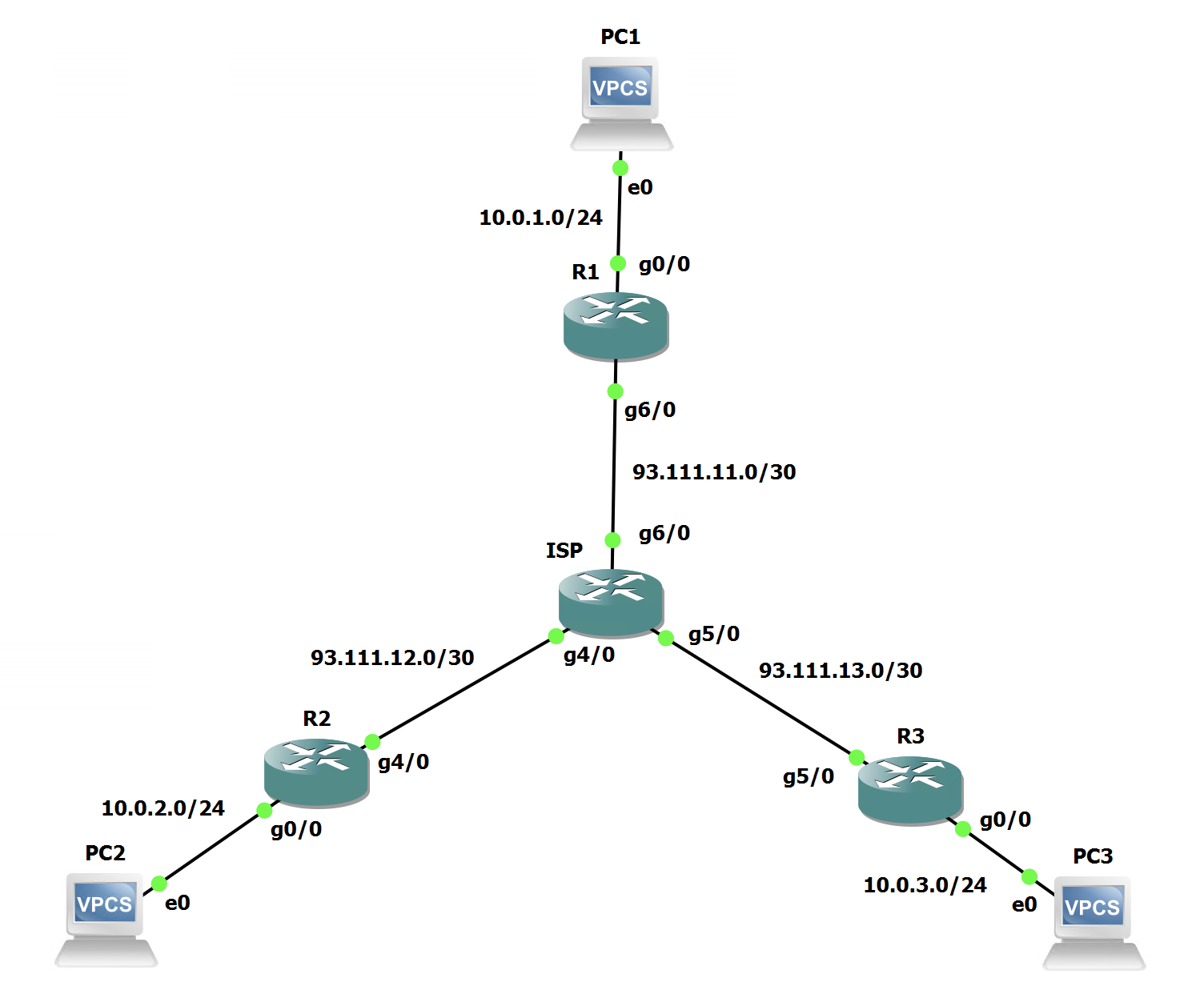
We are currently running Phase 2. So we are forming dynamic spoke-to-spoke tunnels without having the Hub in the data path.
Phase 3 comes into play when we want to do summarisation at the Hub. In this example, the hub is summarising 10.0.0.0/16 down to the spokes. This means that we no longer have different next hops. We go back to the look and feel of Phase 1 where all the routes point to the Hub.
Phase 3 takes this a step further and informs the routers that they are not using the best path to the end host! Let's see how it works and more importantly, how simple it is to implement.
Summarisation Verification
Lets just verify the summarisation on the Hub:
router eigrp Hub
 !
 address-family ipv4 unicast autonomous-system 65001
  !
  af-interface default
   passive-interface
  exit-af-interface
  !
  af-interface Tunnel0
   summary-address 10.0.0.0 255.255.0.0
   no next-hop-self
   no passive-interface
   no split-horizon
  exit-af-interface
  !
  topology base
  exit-af-topology
  network 10.0.1.0 0.0.0.255
  network 192.168.0.0
 exit-address-family
And the routing table on the Spokes proves this:
R2#show ip route eigrp | beg 10
      10.0.0.0/8 is variably subnetted, 3 subnets, 3 masks
D        10.0.0.0/16 [90/76805120] via 192.168.0.1, 00:00:54, Tunnel0
R3#show ip route eigrp | beg 10
10.0.0.0/8 is variably subnetted, 3 subnets, 3 masks
D 10.0.0.0/16 [90/76805120] via 192.168.0.1, 00:01:23, Tunnel0So, when R2 wants to get to the LAN on R3, its next hop is now the Hub, not R3's Tunnel IP. So currently the path from R2 to R3 goes via the Hub.
Hub Configuration - Phase III
The configuration is very simple to move from Phase 2 to 3, its just a single command under the Tunnel interface:
R1(config)#int tunnel0
R1(config-if)#ip nhrp redirect
And thats it! That command is used to allow the Hub to "redirect" the Spokes path.
Spoke Configuration - Phase III
The configuration is very simple to move from Phase 2 to 3, its just a single command under the Tunnel interface:
R2(config)#int tunnel0
R2(config-if)#ip nhrp shortcut
And thats it! That command is used to ensure that when the redirect is triggered by the Hub that the Spoke honours it. This needs to be done on all Spokes.
NHRP Theory - What will happen now?
Like we did with Phase 2, lets dive under the hood of NHRP and see what happens here.
The following will happen:
- R2 does a routing lookup for 10.0.3.0/24 and sees the next-hop is R1 (192.168.0.1)
- R2 sends the packets to R1 as its routing table says so.
- R1 will route the packet(s) to R2 as per its routing table and will also send an NHRP Traffic Indication packet to R2 to inform it of the more optimal path. Packets continue to be routed via R1 while the below happens.
- R2 sends an NHRP Resolution request to R1 for the destination IP address of the packet, not the Tunnel IP.
- R1 forwards that to R3 as per the normal Request/Reply flow.
- R3 sends the NHRP Reply back to R1.
- R3 installs an NHRP Dynamic Mapping for the subnet it was trying to reach (not the Tunnel IP like Phase 2) and also installs an NHRP route in the routing table that will trigger the longest match when more packets egress R2 for R3's LAN segment.
- Any further traffic goes over a dynamic spoke-to-spoke tunnel like Phase 2.
That was a lot to take in... Lets have a look at some packet captures of the process.
This is the NHRP Traffic Indication packet that R1 sent back to R2 when it saw the packet come in via the sub-optimal path:
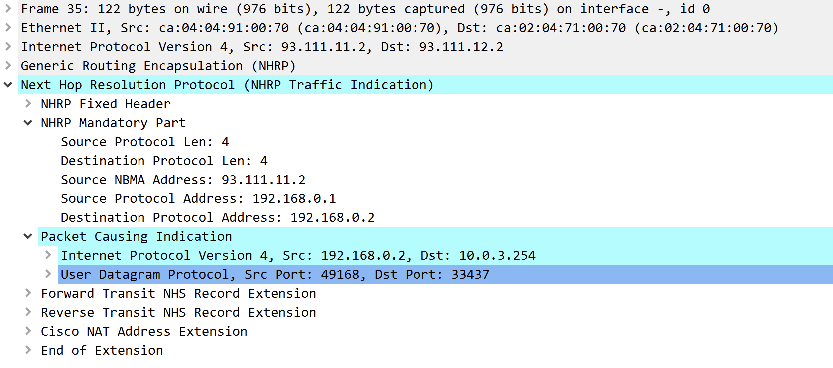
It shows the packet that caused the TI. In this case, it's a UDP traceroute packet. We also see that the packet contains the Destination Protocol Address. However, this is currently R2. This forces R2 to send a NHRP Resolution Request, but slightly different to how Phase 2 did it:
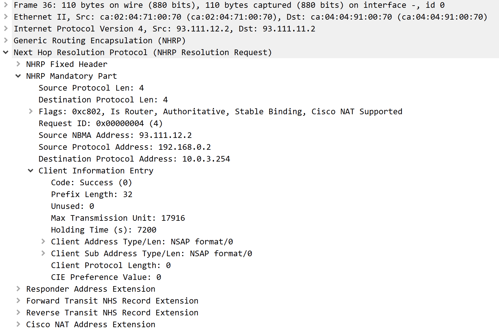
This is the NHRP Request that R2 sends to the Hub. The key difference is that the Destination Protocol Address is the destination IP address from the packet that caused the TI. Rather than a Tunnel IP address. Also notice that under the 'Client Information Entry' the 'Prefix Length' is currently /32.
NHRP then uses the global routing table on the Hub to work out where the traffic needs to go. As the Hub has the specific routes for the Spoke networks:
R1#show ip route eigrp | beg 10
      10.0.0.0/8 is variably subnetted, 5 subnets, 3 masks
D        10.0.0.0/16 is a summary, 00:24:37, Null0
D        10.0.2.0/24 [90/76805120] via 192.168.0.2, 00:33:11, Tunnel0
D        10.0.3.0/24 [90/76805120] via 192.168.0.3, 00:33:11, Tunnel0
R1 knows it needs to forward the NHRP Request to R3. So it forwards the Request as normal to R3.
R3 receives the Request and replies directly to R2 with an NHRP Resolution Reply:
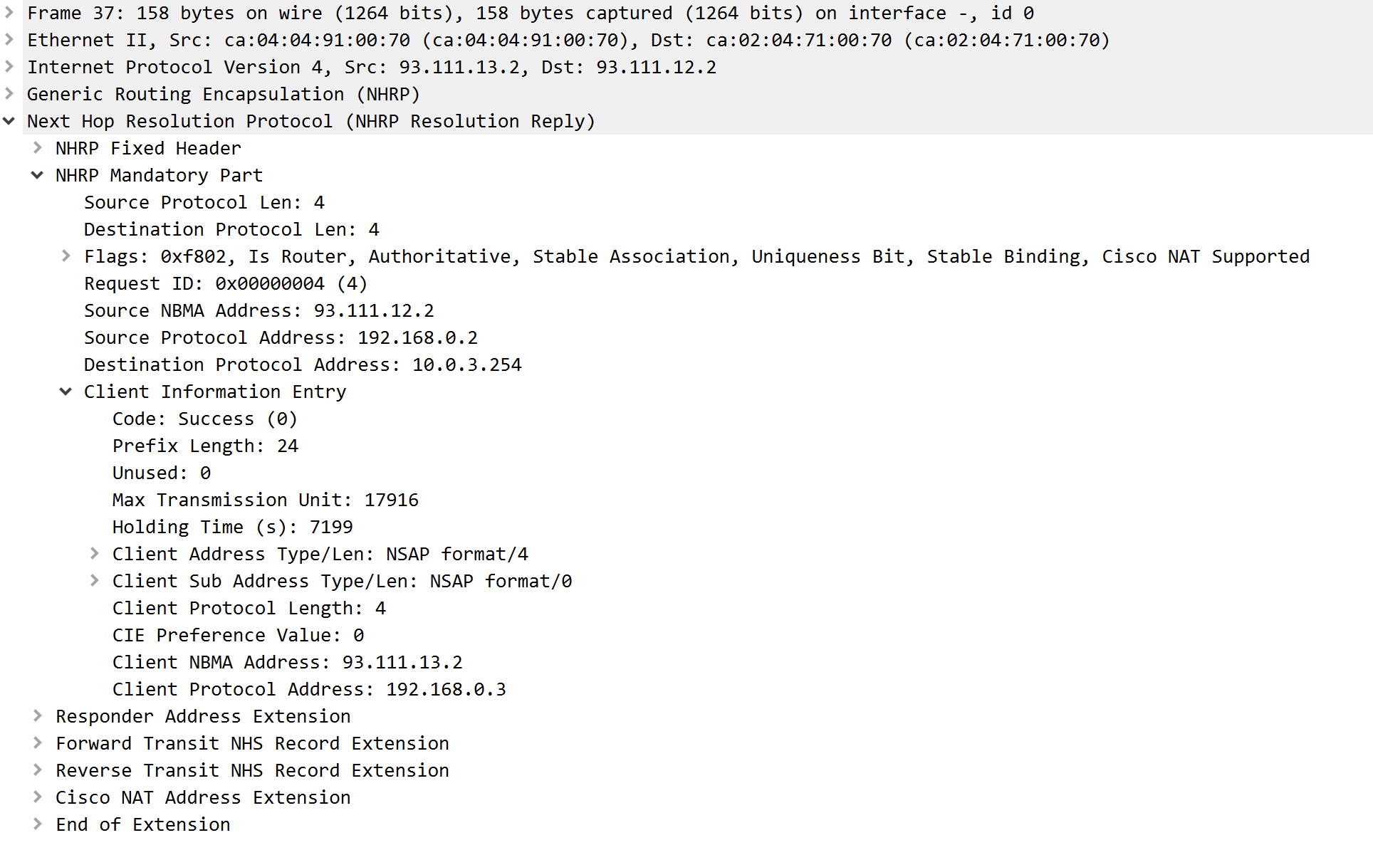
This looks like a standard NHRP Resolution Reply. However we still see that the Destination is set to the LAN IP address on R3. We now also see that the 'Prefix Length' has been changed to 24. This is another great feature of Phase 3, it corrects the subnet so that you don't end up with loads of /32 routes in the Spokes routing tables, and no more traffic to that subnet will trigger a Traffic Indication from the Hub.
When R2 receives this, it does two things, it installs an NHRP route in the routing table and also adds a dynamic NHRP mapping for the prefix:
R2#show ip route 10.0.0.0 255.0.0.0 longer-prefixes | begin 10
      10.0.0.0/8 is variably subnetted, 4 subnets, 3 masks
D        10.0.0.0/16 [90/76805120] via 192.168.0.1, 00:30:36, Tunnel0
C        10.0.2.0/24 is directly connected, GigabitEthernet0/0
L        10.0.2.254/32 is directly connected, GigabitEthernet0/0
H        10.0.3.0/24 [250/1] via 192.168.0.3, 00:22:07, Tunnel0
R2#show ip nhrp
10.0.3.0/24 via 192.168.0.3
   Tunnel0 created 00:22:09, expire 01:37:49
   Type: dynamic, Flags: router used rib
   NBMA address: 93.111.13.2
192.168.0.1/32 via 192.168.0.1
   Tunnel0 created 00:39:23, never expire
   Type: static, Flags: used
   NBMA address: 93.111.11.2
We can see the NHRP route denoted by the 'H' before the route. The next hop for that prefix is R3 which is expected. Interestingly the AD for NHRP is 250 and the metric is 1.
The NHRP dynamic mapping is for the prefix and not the tunnel IP like it was in Phase 2. However, the mapping contains the tunnel IP address of R3 and R3's NBMA Address to form the tunnel.
Finally the dynamic spoke-to-spoke tunnel is created and traffic flows directly between spokes, despite the Hub summarising the subnets.
Final Path Verification
Now we have Phase 3 setup, lets verify the path we are taking by using traceroute:
R2#trace 10.0.3.254 source 10.0.2.254
Type escape sequence to abort.
Tracing the route to 10.0.3.254
VRF info: (vrf in name/id, vrf out name/id)
  1 192.168.0.1 32 msec 28 msec 32 msec
  2 192.168.0.3 64 msec 80 msec 144 msec
R2#trace 10.0.3.254 source 10.0.2.254
Type escape sequence to abort.
Tracing the route to 10.0.3.254
VRF info: (vrf in name/id, vrf out name/id)
  1 192.168.0.3 28 msec 20 msec 20 msec
We can see that this takes a bit longer than Phase 2 to form the tunnel. However, there is no packet loss. The first 3 probes go via the Hub and then to R3, then the next lot go straight to R3 and bypass the Hub!
Thats what we wanted! We now have DMVPN Phase 3 setup and working.

0 Comments