In the last part, we got a multiple tenant VRFs working, in this part, we will look at joining the tenants up via route leaking.
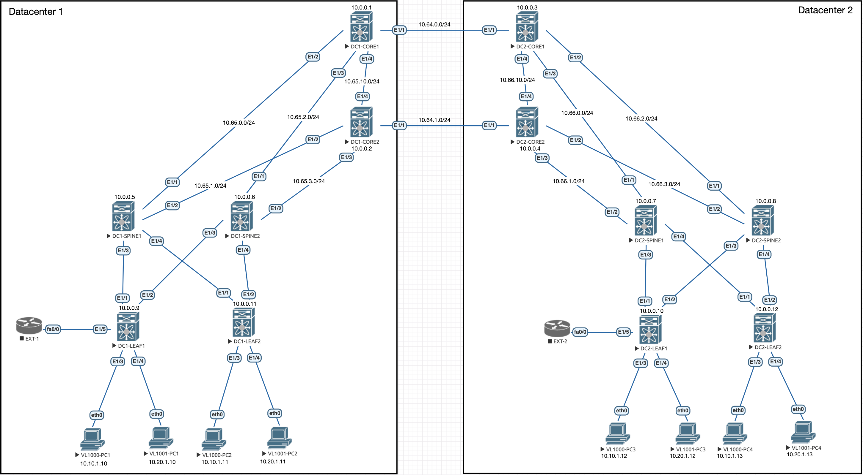
Lets remind ourselves of the topology:
So, currently we have our two VRFs with separate routing tables for vlan 1000 and vlan 1001:
DC1-LEAF1# show ip route vrf overlay-900101

10.10.1.0/24, ubest/mbest: 1/0, attached
    *via 10.10.1.254, Vlan1000, [0/0], 00:57:41, direct
10.10.1.10/32, ubest/mbest: 1/0, attached
    *via 10.10.1.10, Vlan1000, [190/0], 00:23:30, hmm
10.10.1.12/32, ubest/mbest: 1/0
    *via 10.111.111.1%default, [200/2000], 00:34:21, bgp-100, internal, tag 200, segid: 900101 tunnelid: 0xa6f6f01 encap: VXLAN

10.10.1.254/32, ubest/mbest: 1/0, attached
    *via 10.10.1.254, Vlan1000, [0/0], 00:57:41, local
DC1-LEAF1# show ip route vrf overlay-900102
10.20.1.0/24, ubest/mbest: 1/0, attached
*via 10.20.1.254, Vlan1001, [0/0], 00:12:03, direct
10.20.1.11/32, ubest/mbest: 1/0
*via 10.0.0.11%default, [200/0], 00:10:43, bgp-100, internal, tag 100, segid: 900102 tunnelid: 0xa00000b encap: VXLAN
10.20.1.12/32, ubest/mbest: 1/0
*via 10.111.111.1%default, [200/2000], 00:10:35, bgp-100, internal, tag 200, segid: 900102 tunnelid: 0xa6f6f01 encap: VXLAN
10.20.1.254/32, ubest/mbest: 1/0, attached
*via 10.20.1.254, Vlan1001, [0/0], 00:12:03, localVRF Configuration
To do this, we should pick a border leaf that we want to use to complete the leaking per DC, we can leak locally on all leaves, but this can clog up the routing table on the leaves.
In this case, we will use DC1-LEAF2 and DC2-LEAF2 as the border nodes. Lets add some static default routes into the two tenant VRFs on them:
vrf context overlay-900101
  ip route 0.0.0.0/0 Null0
exit
vrf context overlay-900102
  ip route 0.0.0.0/0 Null0
exit
Both VRFs now have a static default route pointed at null0, we need to add the routes within the BGP process:
DC1-LEAF2:
router bgp 100
  vrf overlay-900101
    address-family ipv4 unicast
      network 0.0.0.0/0
  vrf overlay-900102
    address-family ipv4 unicast
      network 0.0.0.0/0
DC2-LEAF2:
router bgp 200
  vrf overlay-900101
    address-family ipv4 unicast
      network 0.0.0.0/0
  vrf overlay-900102
    address-family ipv4 unicast
      network 0.0.0.0/0
We should now see these routes appear on the other leaves:
DC1-LEAF1# show ip route 0.0.0.0 vrf overlay-900101

0.0.0.0/0, ubest/mbest: 1/0
    *via 10.0.0.11%default, [200/0], 00:00:22, bgp-100, internal, tag 100, segid: 900101 tunnelid: 0xa00000b encap: VXLAN
DC1-LEAF1# show ip route 0.0.0.0 vrf overlay-900102
0.0.0.0/0, ubest/mbest: 1/0
*via 10.0.0.11%default, [200/0], 00:00:08, bgp-100, internal, tag 100, segid: 900102 tunnelid: 0xa00000b encap: VXLANCurrently, we still can't communicate between the Tenants because we haven't completed the VRF leaking on the border node:
DC1-LEAF2:
vrf context overlay-900101
  address-family ipv4 unicast
    route-target import 100:900102
    route-target import 100:900102 evpn
vrf context overlay-900102
  address-family ipv4 unicast
    route-target import 100:900101
    route-target import 100:900101 evpn
DC2-LEAF2:
vrf context overlay-900101
  address-family ipv4 unicast
    route-target import 200:900102
    route-target import 200:900102 evpn
vrf context overlay-900102
  address-family ipv4 unicast
    route-target import 200:900101
    route-target import 200:900101 evpn
The above is a little confusing if you look at it for the first time, lets run through what is happening.
Because in our main VRF configuration we have set route-target both auto and route-target both auto evpn. This auto creates the RTs for the VRF, in the case of this environment, the first part of the RT is the ASN and the second part is the VNI assigned to the VRF. Taking this into account, we get the below RTs:
vrf overlay-900101 - bgp-asn:900101
vrf overlay-900102 - bgp-asn:900102
With the rewrite-evpn-rt-asn BGP configuration on the Core switches the RT is re-written when it passes over the DCI to use the local ASN. Hence why the local ASN is only specified and not 100:900102 and 200:900102 on both Border Leaves for example.
Verification
We can confirm these are the correct values by looking at the BGP table:
DC1-LEAF2# show bgp ipv4 unicast 10.10.1.0 vrf overlay-900101
BGP routing table information for VRF overlay-900101, address family IPv4 Unicast
BGP routing table entry for 10.10.1.0/24, version 11
Paths: (2 available, best #1)
Flags: (0x880c0002) (high32 0x000020) on xmit-list, is not in urib, exported
  vpn: version 13, (0x00000000100002) on xmit-list

  Advertised path-id 1, VPN AF advertised path-id 1
  Path type: local, path is valid, is best path, no labeled nexthop, is extd
             Imported to 1 destination(s)
             Imported paths list: overlay-900102
  AS-Path: NONE, path locally originated
    0.0.0.0 (metric 0) from 0.0.0.0 (10.10.1.254)
      Origin IGP, MED not set, localpref 100, weight 32768
      Extcommunity: RT:100:900101 <----------------------------- RT Value

  Path type: internal, path is valid, not best reason: Weight, no labeled nexthop
             Imported from 10.0.0.9:4:[5]:[0]:[0]:[24]:[10.10.1.0]/224
  AS-Path: NONE, path sourced internal to AS
    10.0.0.9 (metric 81) from 10.0.0.5 (10.0.0.5)
      Origin IGP, MED not set, localpref 100, weight 0
      Received label 900101
      Extcommunity: RT:100:900101 ENCAP:8 Router MAC:500a.0000.1b08
      Originator: 10.0.0.9 Cluster list: 10.0.0.5

  VRF advertise information:
  Path-id 1 not advertised to any peer

  VPN AF advertise information:
  Path-id 1 not advertised to any peer
Adding evpn to the end of the second route-target command, ensures that evpn routes are also pulled in with the same RT value. Just leaking the networks is not enough here as the evpn routes will point to a specific leaf where that host is.
Once this configuration is in place, we should see the leaking happening on the border leaves in the route tables:
DC1-LEAF2# show ip route vrf overlay-900101

0.0.0.0/0, ubest/mbest: 1/0
    *via Null0, [1/0], 00:16:09, static
10.10.1.0/24, ubest/mbest: 1/0, attached
    *via 10.10.1.254, Vlan1000, [0/0], 01:15:19, direct
10.10.1.10/32, ubest/mbest: 1/0
    *via 10.0.0.9%default, [200/0], 01:10:29, bgp-100, internal, tag 100, segid: 900101 tunnelid: 0xa000009 encap: VXLAN

10.10.1.12/32, ubest/mbest: 1/0
    *via 10.111.111.1%default, [200/2000], 00:52:02, bgp-100, internal, tag 200, segid: 900101 tunnelid: 0xa6f6f01 encap: VXLAN

10.10.1.254/32, ubest/mbest: 1/0, attached
    *via 10.10.1.254, Vlan1000, [0/0], 01:15:19, local
10.20.1.0/24, ubest/mbest: 1/0, attached
    *via 10.20.1.254%overlay-900102, Vlan1001, [20/0], 00:08:56, bgp-100, external, tag 100
10.20.1.12/32, ubest/mbest: 1/0
    *via 10.111.111.1%default, [200/2000], 00:08:56, bgp-100, internal, tag 200, segid: 900102 (Asymmetric) tunnelid: 0xa6f6f01 encap: VXLAN

DC1-LEAF2# show ip route vrf overlay-900102

0.0.0.0/0, ubest/mbest: 1/0
    *via Null0, [1/0], 00:16:11, static
10.10.1.0/24, ubest/mbest: 1/0, attached
    *via 10.10.1.254%overlay-900101, Vlan1000, [20/0], 00:08:58, bgp-100, external, tag 100
10.10.1.10/32, ubest/mbest: 1/0
    *via 10.0.0.9%default, [200/0], 00:08:58, bgp-100, internal, tag 100, segid: 900101 (Asymmetric) tunnelid: 0xa000009 encap: VXLAN

10.10.1.12/32, ubest/mbest: 1/0
    *via 10.111.111.1%default, [200/2000], 00:08:58, bgp-100, internal, tag 200, segid: 900101 (Asymmetric) tunnelid: 0xa6f6f01 encap: VXLAN

10.20.1.0/24, ubest/mbest: 1/0, attached
    *via 10.20.1.254, Vlan1001, [0/0], 00:29:42, direct
10.20.1.11/32, ubest/mbest: 1/0, attached
    *via 10.20.1.11, Vlan1001, [190/0], 00:29:42, hmm
10.20.1.12/32, ubest/mbest: 1/0
    *via 10.111.111.1%default, [200/2000], 00:28:16, bgp-100, internal, tag 200, segid: 900102 tunnelid: 0xa6f6f01 encap: VXLAN

10.20.1.254/32, ubest/mbest: 1/0, attached
    *via 10.20.1.254, Vlan1001, [0/0], 00:29:42, local
We can see from the above that within each VRF, we see the other VRFs routes, this is as per the VRF leaking we configured.
We should also have connectivity between the Tenants:
VPCS> show ip

NAME        : VPCS[1]
IP/MASK     : 10.10.1.10/24
GATEWAY     : 10.10.1.254
DNS         :
MAC         : 00:50:79:66:68:01
LPORT       : 20000
RHOST:PORT  : 127.0.0.1:30000
MTU         : 1500

VPCS> ping 10.20.1.12

84 bytes from 10.20.1.12 icmp_seq=1 ttl=59 time=65.651 ms
84 bytes from 10.20.1.12 icmp_seq=2 ttl=59 time=31.913 ms
84 bytes from 10.20.1.12 icmp_seq=3 ttl=59 time=27.500 ms
84 bytes from 10.20.1.12 icmp_seq=4 ttl=59 time=38.756 ms
84 bytes from 10.20.1.12 icmp_seq=5 ttl=59 time=24.598 ms
Thats what we expected! Of course you can be more specific on the route leaking by using import and export maps to only leak specific subnets between the tenants.
In the next part we will look at allowing external access to other resources outside of the fabric.

0 Comments