In the last part, we got a single tenant VRF working, in this part, we will look at splitting vlan 1001 off into its own separate Tenant to show a multi-tenant setup.
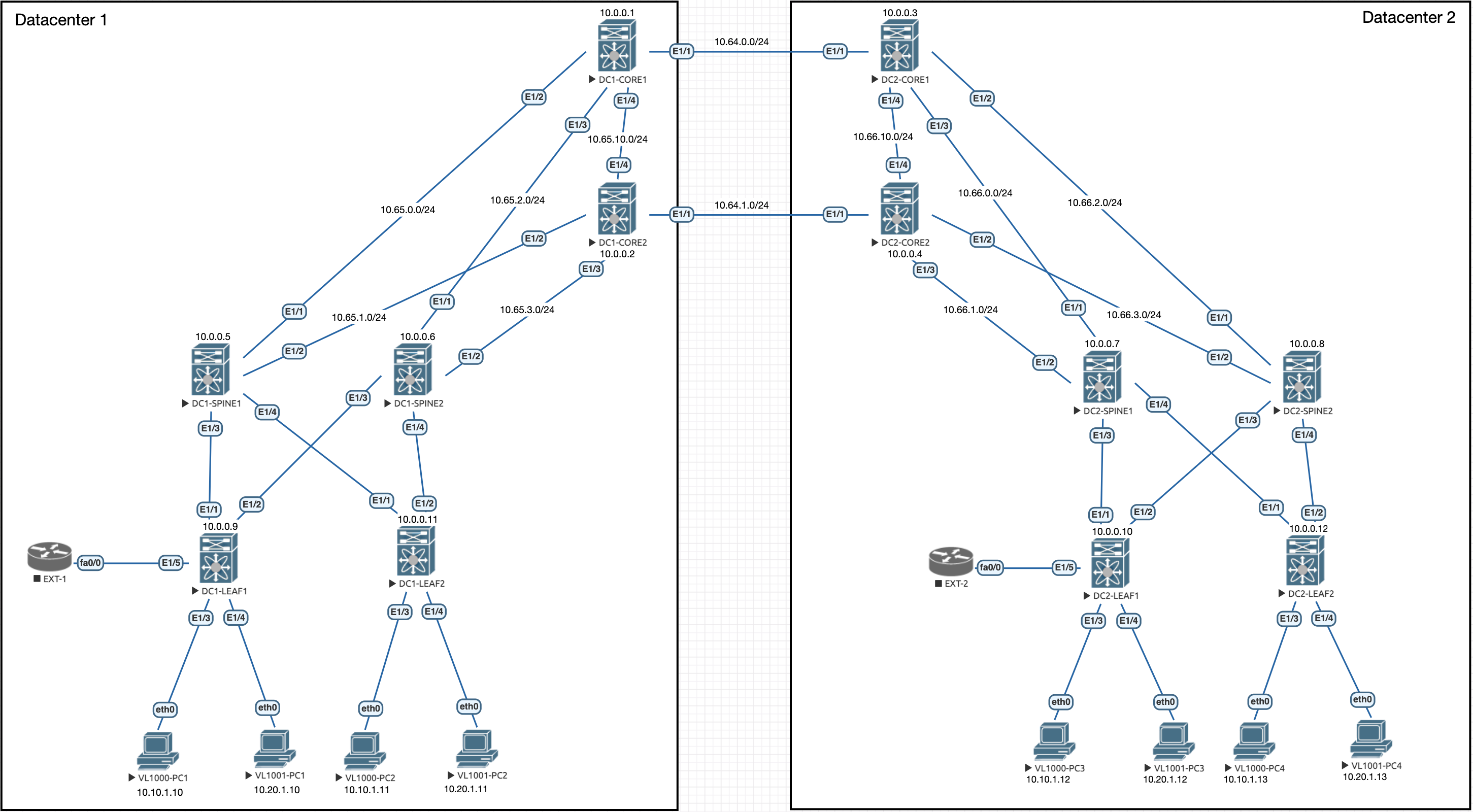
Lets remind ourselves of the topology:
All of the configuration below is for the Leaves in the topology.
Vlan Configuration - Leaves and Core Switches
Firstly, we need to configure another L3VNI vlan for the routing in this new tenant:
vlan 998
  vn-segment 900102
VRF Configuration - Leaves and Core Switches
We also need another tenant VRF to be configured which will house the overlay routing:
vrf context overlay-900102
  vni 900102
  rd auto
  address-family ipv4 unicast
    route-target both auto
    route-target both auto evpn
This configuration also brings in the EVPN information too.
We should also move the SVI for Vlan 1001 over to the new VRF and add the Layer 3 info back in:
interface Vlan1001
  vrf member overlay-900102
  ip address 10.20.1.254/24
  fabric forwarding mode anycast-gateway
SVI and NVE Configuration - Leaves and Core Switches
We also need to setup a new L3VNI SVI on the Leaves and Cores. This is a duplicate of what Vlan999 was used for in the last part. With multi-tenant setups we need a separate L3VNI for it:
interface Vlan998
  no shutdown
  vrf member overlay-900102
  ip forward
We also need to add the VNI to the original nve interface:
interface nve1
  member vni 900102 associate-vrf
BGP Configuration
The final part is the BGP configuration, we need to put in the new VRF but also make sure we remove the vlan 20 network from being advertised in the other VRF:
DC1:
router bgp 100
  vrf overlay-900101
    address-family ipv4 unicast
      no network 10.20.1.0/24
  vrf overlay-900102
    log-neighbor-changes
    address-family ipv4 unicast
      network 10.20.1.0/24
DC2:
router bgp 200
  vrf overlay-900101
    address-family ipv4 unicast
      no network 10.20.1.0/24
  vrf overlay-900102
    log-neighbor-changes
    address-family ipv4 unicast
      network 10.20.1.0/24
Verification
At this point, we need to give BGP some time to converge and then we can see the separate BGP tables:
DC1-LEAF1# show bgp ipv4 unicast vrf overlay-900101 | beg Network
   Network            Next Hop            Metric     LocPrf     Weight Path
* i10.10.1.0/24       10.0.0.11                         100          0 i
*>l                   0.0.0.0                           100      32768 i
*>i10.10.1.12/32      10.111.111.1          2000        100          0 200 i

lDC1-LEAF1# show bgp ipv4 unicast vrf overlay-900102 | beg Network
   Network            Next Hop            Metric     LocPrf     Weight Path
* i10.20.1.0/24       10.0.0.11                         100          0 i
*>l                   0.0.0.0                           100      32768 i
*>i10.20.1.11/32      10.0.0.11                         100          0 i
*>i10.20.1.12/32      10.111.111.1          2000        100          0 200 i
Here we can see that DC1-LEAF1 knows about 10.20.1.0/24 (Vlan1001) from DC1-LEAF2, and its being locally originated. We don't see the routes originated from the other DC because they aren't the best path on the core switches due to BGP path selection. So these routes will stay with the Core switches.
We should still have layer 2 connectivity within the VNIs but we should have broken layer 3 connectivity between the two vlans because they reside in separate tenants:
VPCS> show ip

NAME        : VPCS[1]
IP/MASK     : 10.10.1.10/24
GATEWAY     : 10.10.1.254
DNS         :
MAC         : 00:50:79:66:68:01
LPORT       : 20000
RHOST:PORT  : 127.0.0.1:30000
MTU         : 1500

VPCS> ping 10.20.1.12

10.20.1.12 icmp_seq=1 timeout
10.20.1.12 icmp_seq=2 timeout
10.20.1.12 icmp_seq=3 timeout
10.20.1.12 icmp_seq=4 timeout
10.20.1.12 icmp_seq=5 timeout

VPCS> ping 10.10.1.12

84 bytes from 10.10.1.12 icmp_seq=1 ttl=64 time=23.879 ms
84 bytes from 10.10.1.12 icmp_seq=2 ttl=64 time=23.148 ms
84 bytes from 10.10.1.12 icmp_seq=3 ttl=64 time=20.276 ms
84 bytes from 10.10.1.12 icmp_seq=4 ttl=64 time=22.913 ms
84 bytes from 10.10.1.12 icmp_seq=5 ttl=64 time=21.231 ms
This is what we expected, the tenants are now separate. However, there are ways to regain communications between the networks despite them being in different tenants. This may be required in some topologies. We will explore this in the next part. From the above we have confirmed that we still have intra-VNI connectivity though!

0 Comments