In this post, I am going to show the process of using PIM BiDir Phantom RP in the VXLAN EVPN topology we build in Parts 1 to 8 here.
PIM is an important part of the VXLAN underlay as its used to route BUM (Broadcast, Unknown Unicast and Multicast) traffic. Even if we have ARP Suppression enabled (which the guides do show). While technically, you could get the fabric working without PIM, but all hosts would have to generate some traffic to populate the ARP Suppression Cache. Once a MAC and IP get populated locally, these will be sent to the spine RRs using BGP and make its way to all the other VTEPs, negating the need for PIM. Lets face it though, thats not realistic in modern networks, we have plenty of devices denoted as Silent Hosts that we need to be able to flood traffic to in order to get a response.
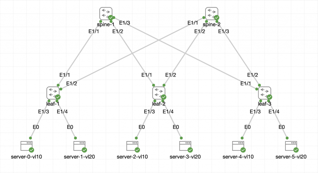
Here is the topology we will be working with:
 The switches are all Nexus C9300v running NX-OS version 10.3(5).
Phantom RP is an interesting and honestly quite neat way of implementing RPs. It involves strategically manipulating the subnet mask of the RP Loopbacks between your Spines in order to make one primary and the other secondary. That is an important distinction here, unlike with Anycast RP, where both Spines can service traffic at the same time, Phantom RP has no load sharing mechanism on a single RP address. However, we can get around this by creating a 2nd RP which we will do later on.
The Phantom part of the name comes where the IP of the RP we setup, isn't the IP configured on the loopbacks, but is an IP address in the subnet instead. Hence the RP isn't directly configured on the interface.
Anyway, lets configure it!
Multicast Configuration
PIM is configured for the VXLAN Flood and Learn mechanism and in this topology, we will need to configure the spines to be RPs.
In this example, we will make spine-1 the primary RP for this mcast group.
The configuration on spine-1 should be:
ip pim rp-address 10.99.99.100 group-list 238.0.0.0/24 bidir

interface loopback1
  ip address 10.99.99.99/29
  ip ospf network point-to-point
  ip router ospf UNDERLAY area 0.0.0.0
  ip pim sparse-mode

interface loopback0
  ip pim sparse-mode

int Ethernet1/1-3
  ip pim sparse-mode
The configuration on spine-2 should be:
ip pim rp-address 10.99.99.100 group-list 238.0.0.0/24 bidir

interface loopback1
  ip address 10.99.99.99/28
  ip ospf network point-to-point
  ip router ospf UNDERLAY area 0.0.0.0
  ip pim sparse-mode

interface loopback0
  ip pim sparse-mode

int Ethernet1/1-3
  ip pim sparse-mode
Here we can see the difference in the subnet masks on the loopbacks. If we do a route lookup for the RP address on a leaf, we can see which its going to use:
leaf-1# show ip route 10.99.99.100
IP Route Table for VRF "default"
'*' denotes best ucast next-hop
'**' denotes best mcast next-hop
'[x/y]' denotes [preference/metric]
'%<string>' in via output denotes VRF <string>

10.99.99.96/29, ubest/mbest: 1/0
    *via 10.0.0.1, Eth1/1, [110/41], 01:23:34, ospf-UNDERLAY, intra
This is going via spine-1 as we expect. However, if we dig deeper into the route table, we should see the other route via spine-2
leaf-1# show ip route | inc 10.99.99.96 next 1
10.99.99.96/28, ubest/mbest: 1/0
    *via 10.0.0.2, Eth1/2, [110/41], 01:49:30, ospf-UNDERLAY, intra
10.99.99.96/29, ubest/mbest: 1/0
    *via 10.0.0.1, Eth1/1, [110/41], 01:26:20, ospf-UNDERLAY, intra
And we do see that there. At this point, its simple longest match routing, for the RP, we are going to choose the /29. However, if the /29 went away (spine-1 failed or had a problem) then the /28 will still get us there. So while this isn't doing load sharing, its 100% fault tolerant.
The configuration on the leaves is a little less involved:
ip pim rp-address 10.99.99.100 group-list 238.0.0.0/24 bidir

interface loopback0
  ip pim sparse-mode

interface Ethernet1/1-2
  ip pim sparse-mode
We need to make sure that any mcast-group entries under the nve1 interface now use an address within the 238.0.0.0/24 range in order for them to use this Phantom RP. That was covered in Part 3 of the main guide. So watch out for that.
We can validate the Multicast setup with the following command on the spines:
spine-1# show ip pim rp
PIM RP Status Information for VRF "default"
BSR disabled
Auto-RP disabled
BSR RP Candidate policy: None
BSR RP policy: None
Auto-RP Announce policy: None
Auto-RP Discovery policy: None

RP: 10.99.99.100, (1),
 uptime: 01:36:38   priority: 255,
 RP-source: (local),
 group ranges:
 238.0.0.0/24  (bidir)
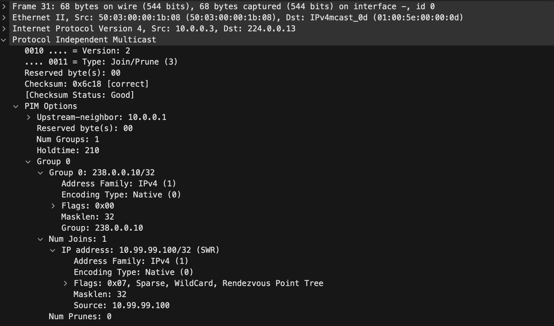
Once a VNI is configured like you would normally setup and the multicast IP used falls within the range specified for the RP, the VTEP will send a PIM join to the RP:

This PIM Join was sent to the well known All PIM Routers address 224.0.0.13 and within the packet we can see that it is indeed a Join message for the group 238.0.0.10/32 which is using the RP of 10.99.99.100/32.
If we check the multicast routing table on leaf-1 we should see an entry for 238.0.0.10/32:
leaf-1# show ip mroute 238.0.0.10
IP Multicast Routing Table for VRF "default"

(*, 238.0.0.10/32), bidir, uptime: 02:16:25, ip pim nve
  Incoming interface: Ethernet1/1, RPF nbr: 10.0.0.1
  Outgoing interface list: (count: 2)
    nve1, uptime: 00:19:38, nve
    Ethernet1/1, uptime: 02:00:01, pim, (RPF)
The above output from the leaf shows its joined the mcast group and it shows the interface in which it needs to use to get there and forward traffic towards. In this case using Ethernet1/1.
If we do that same command on spine-1 we should see a similar output:
spine-1# show ip mroute 238.0.0.10
IP Multicast Routing Table for VRF "default"

(*, 238.0.0.10/32), bidir, uptime: 02:07:30, pim ip
  Incoming interface: loopback1, RPF nbr: 10.99.99.100
  Outgoing interface list: (count: 4)
    Ethernet1/1, uptime: 00:31:35, pim
    Ethernet1/3, uptime: 02:07:30, pim
    Ethernet1/2, uptime: 02:07:30, pim
    loopback1, uptime: 02:07:30, pim, (RPF)
This output has some more outgoing interfaces because other VTEPs have also joined the group. So this spine knows how to forward the traffic if it received a packet destined for the group IP.
Proving the path with PCAPs
So just to round off, lets have a look at some BUM traffic under the microscope with wireshark.
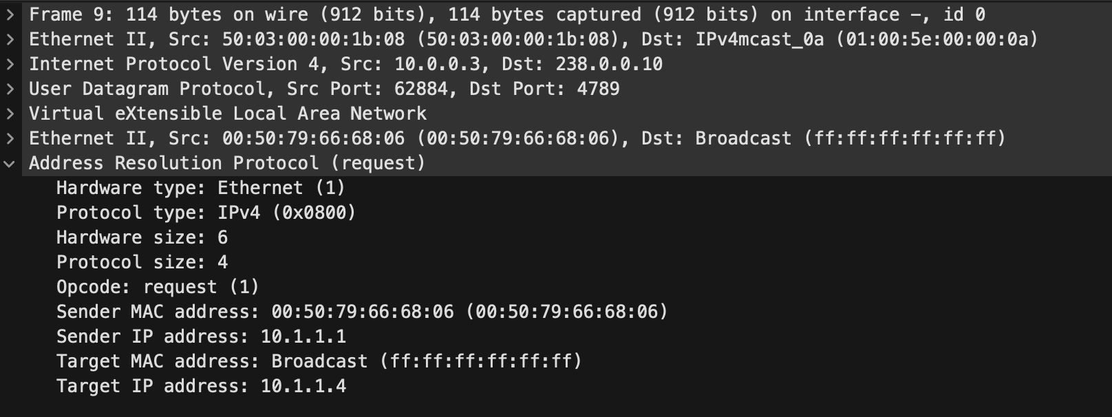
A device on Vlan10 (VNI 100010) connected to leaf-1 with the IP address 10.1.1.1 is trying to communicate with 10.1.1.4 which is a silent host connected to leaf-3. Hence the IP 10.1.1.4 isn't in any ARP suppression cache tables. This is classed as unknown unicast. Either way, the host on leaf-1 will send an ARP broadcast out:

We can see in the above that the destination for this ARP packet in the underlay is 238.0.0.10 which is the mcast-group configured for the VNI. We know this is being served by the RP on spine-1 so this packet was seen going up from leaf-1 to spine-1.
From there, the spine will look at its multicast routing table and will send it outbound to all of the interfaces it had listed in the output above, except the one it came in on. So we should have seen this packet land on all the leaf VTEPs that have this VNI configured.
Looking at the capture for leaf-3 we can see the ARP broacast made it there:

Its also accompanied by a ARP response from the end-host. The ARP broadcast itself is still destined for the multicast IP. However, the response is direct unicast between the VTEPs because the VTEPs now know where the hosts are and they can send directly rather than having to send the response back via multicast:

In this case 10.0.0.3 is leaf-1 and 10.0.0.5 is leaf-3 and there is no trace of the multicast IP.
At this point, we would expect the ARP Suppression Cache to have been updated and a remote entry would appear on leaf-1 for 10.1.1.4 so any further unicast traffic between them will not class as BUM and won't use our Multicast Infrastructure.
Conclusion
PIM Phantom RP is pretty cool, but there is one issue that you can probably see. If we had a lot of BUM traffic in our environment, its all going to one spine as the RP, as there is no load sharing. In another part, I will explain how we can add another RP and manipulate the multicast IPs for our VNIs to manually load share between the two spines while still keeping the notion of fault tolerance so if a spine failed, we still have an RP.

0 Comments