In this series of guides, we will be completing the setup of a VXLAN fabric. In this part, we will look at the topology and setup the underlay network using OSPF.
Here is the topology we will be working with:
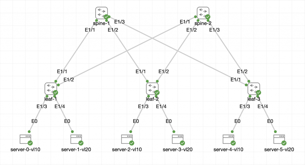 The switches are all Nexus C9300v running NX-OS version 9.3(8).
Firstly we should enable all the features we need for the configuration on all switches:
feature ospf
feature bgp
feature pim
feature fabric forwarding
feature interface-vlan
feature vn-segment-vlan-based
feature nv overlay
Each of the switches have a lookback0 interface configured with IP addresses:
spine-1: 10.0.0.1/32
spine-2: 10.0.0.2/32
leaf-1: 10.0.0.3/32
leaf-2: 10.0.0.4/32
leaf-3: 10.0.0.5/32
Routing Configuration
All switches have a basic OSPF configuration:
router ospf UNDERLAY
  log-adjacency-changes
Then each of the loopback0 interfaces are configured for OSPF in area 0.0.0.0:
interface Loopback0
  ip router ospf UNDERLAY area 0.0.0.0
Interface Configuration
The Spine interfaces towards the the leaves are configured as layer 3 ports using the loopback interface:
interface Ethernet1/1-3
  no switchport
  mtu 9216
  medium p2p
  ip unnumbered loopback0
  ip router ospf UNDERLAY area 0.0.0.0
The Leaf interfaces towards the the spines are also configured as layer 3 ports using the loopback interface:
interface Ethernet1/1-2
  no switchport
  mtu 9216
  medium p2p
  ip unnumbered loopback0
  ip router ospf UNDERLAY area 0.0.0.0
We should now have basic connectivity within the topology, lets check the routing table on spine-1 for the OSPF routes:
spine-1# show ip route ospf-UNDERLAY
IP Route Table for VRF default

10.0.0.2/32, ubest/mbest: 3/0
    *via 10.0.0.3, Eth1/1, [110/81], 00:00:08, ospf-UNDERLAY, intra
    *via 10.0.0.4, Eth1/2, [110/81], 00:00:08, ospf-UNDERLAY, intra
    *via 10.0.0.5, Eth1/3, [110/81], 00:00:13, ospf-UNDERLAY, intra
10.0.0.3/32, ubest/mbest: 1/0
    *via 10.0.0.3, Eth1/1, [110/41], 00:00:14, ospf-UNDERLAY, intra
10.0.0.4/32, ubest/mbest: 1/0
    *via 10.0.0.4, Eth1/2, [110/41], 00:00:14, ospf-UNDERLAY, intra
10.0.0.5/32, ubest/mbest: 1/0
    *via 10.0.0.5, Eth1/3, [110/41], 00:00:14, ospf-UNDERLAY, intra
The above shows that we are seeing all the correct routes in the underlay. Now we can move onto the Multicast setup.
Multicast Configuration
PIM is configured for the VXLAN Flood and Learn mechanism and in this topology, we will need to configure the spines to be RPs.
The configuration on the spines should be:
ip pim rp-address 10.0.0.99 group-list 224.0.0.0/4
ip pim ssm range 232.0.0.0/8
ip pim anycast-rp 10.0.0.99 10.0.0.1
ip pim anycast-rp 10.0.0.99 10.0.0.2

interface loopback1
  ip address 10.0.0.99/32
  ip router ospf UNDERLAY area 0.0.0.0
  ip pim sparse-mode

interface loopback0
  ip pim sparse-mode

int Ethernet1/1-3
  ip pim sparse-mode
The configuration on the leaves is a little less involved:
ip pim rp-address 10.0.0.99 group-list 224.0.0.0/4
ip pim ssm range 232.0.0.0/8

interface loopback0
  ip pim sparse-mode

interface Ethernet1/1-2
  ip pim sparse-mode
This configurations makes the spines both RPs with the address 10.0.0.99 and then configures the leaves to point towards them. Making the setup and topology redundant.
We can validate the Multicast setup with the following command on the spines:
spine-1(config)# show ip pim rp
PIM RP Status Information for VRF default
BSR disabled
Auto-RP disabled
BSR RP Candidate policy: None
BSR RP policy: None
Auto-RP Announce policy: None
Auto-RP Discovery policy: None

Anycast-RP 10.0.0.99 members:
  10.0.0.1*  10.0.0.2

RP: 10.0.0.99*, (0),
 uptime: 00:07:03   priority: 255,
 RP-source: (local),
 group ranges:
 224.0.0.0/4
We can see from the above output that the multicast setup is working and both RPs can see each other.
Now we can look at the final part of the underlay setup with the NVE setup.
NVE Configuration
NVE (Network Virtual Endpoint) is a logical interface where the encapsulation and de-encapsulation happens. This configuration is for the leaves only as they are the ones doing the encapsulation and de-encapsulation. It is also called the VTEP which stands for Virtual Tunnel Endpoint.
This is the base configuration for the nve1 interface:
interface nve1
  no shutdown
  host-reachability protocol bgp
  source-interface loopback0
We can check the status of the nve interface:
leaf-1# show interface nve 1
nve1 is up
admin state is up,  Hardware: NVE
  MTU 9216 bytes
  Encapsulation VXLAN
  Auto-mdix is turned off
  RX
    ucast: 0 pkts, 0 bytes - mcast: 0 pkts, 0 bytes
  TX
    ucast: 0 pkts, 0 bytes - mcast: 0 pkts, 0 bytes
The above output shows the interface is in an UP state.
We are done with the underlay setup now, and we will move onto the overlay configuration in the next part.

0 Comments