I am going to walk through how the LSP (Label Switched Path) is found on Cisco devices running LDP and go through a practical demonstration.
First, lets look at our topology:
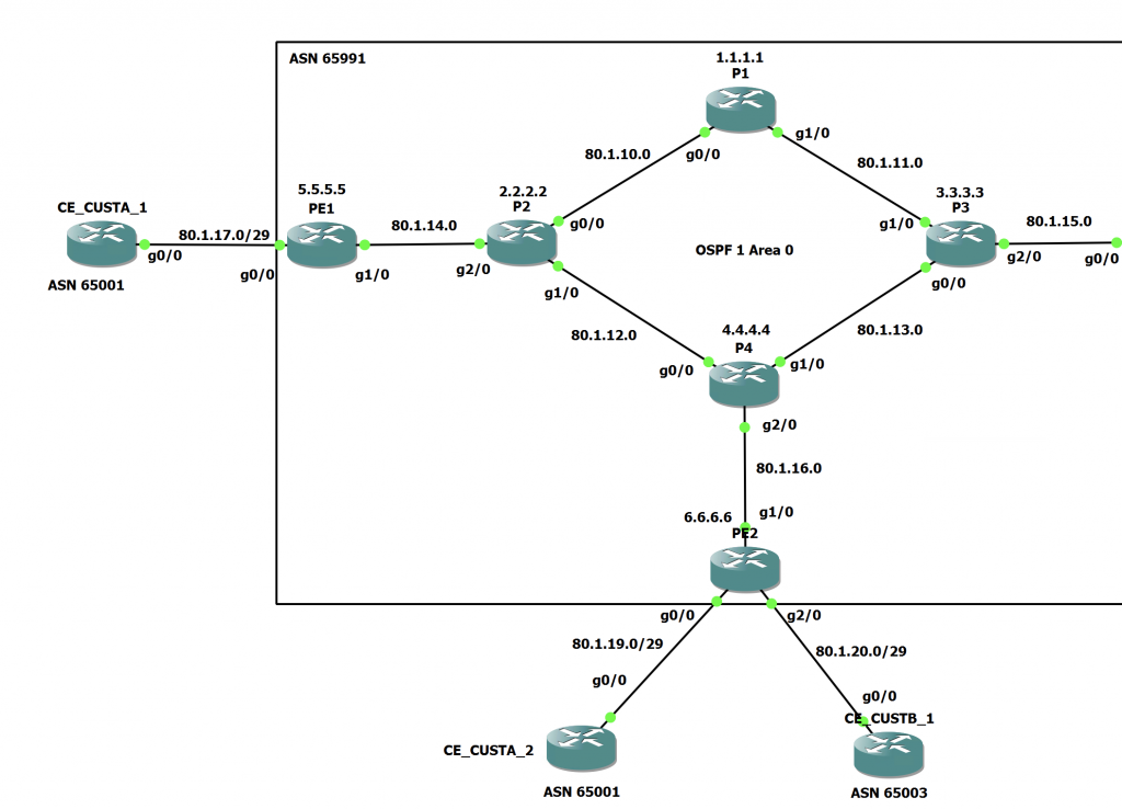
In this demonstration we are looking at the path for traffic originating from CE_CUSTA_2 to CE_CUSTA_1.
Let's look at the configurations so you can see how this network is setup.
P1 is a Provider Core Router that is acting as a BGP Route Reflector, its configuration is as follows:
P1#sh run | sect bgp
router bgp 65991
 bgp router-id 1.1.1.1
 bgp log-neighbor-changes
 no bgp default ipv4-unicast
 ! PE1 iBGP Peering
 neighbor 5.5.5.5 remote-as 65991
 neighbor 5.5.5.5 update-source Loopback0
 ! PE2 iBGP Peering
 neighbor 6.6.6.6 remote-as 65991
 neighbor 6.6.6.6 update-source Loopback0
 !
 address-family ipv4
  neighbor 5.5.5.5 activate
  neighbor 6.6.6.6 activate
  neighbor 5.5.5.5 route-reflector-client
  neighbor 6.6.6.6 route-reflector-client
 exit-address-family
P1#sh run | sect ospf
router ospf 1
 router-id 1.1.1.1
 network 1.1.1.1 0.0.0.0 area 0
 network 80.1.0.0 0.0.255.255 area 0
 mpls ldp autoconfig
P1#sh ip int br
Interface              IP-Address      OK? Method Status                Protocol
GigabitEthernet0/0     80.1.10.1       YES NVRAM  up                    up
GigabitEthernet1/0     80.1.11.1       YES NVRAM  up                    up
Loopback0              1.1.1.1         YES NVRAM  up                    up
P2 is also a Provider Core Router. However, as this topology has a BGP Free Core, it is only running OSPF:
P2#sh run | sect bgp
P2#sh run | sect ospf
router ospf 1
 router-id 2.2.2.2
 network 2.2.2.2 0.0.0.0 area 0
 network 80.1.0.0 0.0.255.255 area 0
 mpls ldp autoconfig
P2#sh ip int br
Interface              IP-Address      OK? Method Status                Protocol
GigabitEthernet0/0     80.1.10.2       YES NVRAM  up                    up
GigabitEthernet1/0     80.1.12.1       YES NVRAM  up                    up
GigabitEthernet2/0     80.1.14.1       YES NVRAM  up                    up
Loopback0              2.2.2.2         YES NVRAM  up                    up
The same story is also present on P4. Its a Provider Core Router running in the BGP Free Core:
P4#sh run | sect bgp
P4#sh run | sect ospf
router ospf 1
 router-id 4.4.4.4
 network 4.4.4.4 0.0.0.0 area 0
 network 80.1.0.0 0.0.255.255 area 0
 mpls ldp autoconfig
P4#sh ip int br
Interface              IP-Address      OK? Method Status                Protocol
GigabitEthernet0/0     80.1.12.2       YES NVRAM  up                    up
GigabitEthernet1/0     80.1.13.2       YES NVRAM  up                    up
GigabitEthernet2/0     80.1.16.1       YES NVRAM  up                    up
Loopback0              4.4.4.4         YES NVRAM  up                    up
PE1 is a Provider Edge Router and has a BGP Peering with the Customer too:
PE1#sh run | sect bgp
router bgp 65991
 bgp router-id 5.5.5.5
 bgp log-neighbor-changes
 no bgp default ipv4-unicast
 ! P1 iBGP Peering
 neighbor 1.1.1.1 remote-as 65991
 neighbor 1.1.1.1 update-source Loopback0
 ! CE_CUSTB_1 eBGP Peering
 neighbor 80.1.17.2 remote-as 65001
 !
 address-family ipv4
  neighbor 1.1.1.1 activate
  neighbor 1.1.1.1 next-hop-self
  neighbor 80.1.17.2 activate
  neighbor 80.1.17.2 default-originate
 exit-address-family
PE1#sh run | sect ospf
router ospf 1
 router-id 5.5.5.5
 passive-interface default
 no passive-interface GigabitEthernet1/0
 network 5.5.5.5 0.0.0.0 area 0
 network 80.1.14.0 0.0.0.3 area 0
 mpls ldp autoconfig
PE1#sh ip int br
Interface              IP-Address      OK? Method Status                Protocol
GigabitEthernet0/0     80.1.17.1       YES NVRAM  up                    up
GigabitEthernet1/0     80.1.14.2       YES NVRAM  up                    up
Loopback0              5.5.5.5         YES NVRAM  up                    up
Loopback1              unassigned      YES unset  up                    up
PE2 is the same. A Provider Edge router with a peering to the Customer (I have omitted the peering with CE_CUSTB_2 as that isn't required for this):
PE2#sh run | sect bgp
router bgp 65991
 bgp router-id 6.6.6.6
 bgp log-neighbor-changes
 no bgp default ipv4-unicast
 ! P1 iBGP Peering
 neighbor 1.1.1.1 remote-as 65991
 neighbor 1.1.1.1 update-source Loopback0
 ! CE_CUSTB_2 eBGP Peering
 neighbor 80.1.19.2 remote-as 65002
 !
 address-family ipv4
  neighbor 1.1.1.1 activate
  neighbor 1.1.1.1 next-hop-self
  neighbor 80.1.19.2 activate
  neighbor 80.1.19.2 default-originate
 exit-address-family
PE2#sh run | sect ospf
router ospf 1
 router-id 6.6.6.6
 passive-interface default
 no passive-interface GigabitEthernet1/0
 network 6.6.6.6 0.0.0.0 area 0
 network 80.1.16.0 0.0.0.3 area 0
 mpls ldp autoconfig
PE2#sh ip int br
Interface              IP-Address      OK? Method Status                Protocol
GigabitEthernet0/0     80.1.19.1       YES NVRAM  up                    up
GigabitEthernet1/0     80.1.16.2       YES NVRAM  up                    up
GigabitEthernet2/0     80.1.20.1       YES NVRAM  up                    up
Loopback0              6.6.6.6         YES NVRAM  up                    up
Finally, lets look at the two CE Routers
CE_CUSTA_1:
CE_CUSTA_1#sh run | sect bgp
router bgp 65001
 bgp router-id 80.1.17.2
 bgp log-neighbor-changes
 no bgp default ipv4-unicast
 ! PE1 eBGP Peering
 neighbor 80.1.17.1 remote-as 65991
 !
 address-family ipv4
  neighbor 80.1.17.1 activate
  network 80.1.17.0 mask 255.255.255.248
 exit-address-family
CE_CUSTA_1#sh ip int br
Interface              IP-Address      OK? Method Status                Protocol
GigabitEthernet0/0     80.1.17.2       YES NVRAM  up                    up
Loopback0              10.1.1.1        YES NVRAM  up                    up
CE_CUSTA_1#sh ip nat statistics
Outside interfaces:
  GigabitEthernet0/0
Inside interfaces:
  Loopback0
CE_CUSTA_2:
CE_CUSTA_2#sh run | sect bgp
router bgp 65002
 bgp router-id 80.1.19.2
 bgp log-neighbor-changes
 no bgp default ipv4-unicast
 ! PE2 eBGP Peering
 neighbor 80.1.19.1 remote-as 65991
 !
 address-family ipv4
  network 80.1.19.0 mask 255.255.255.248
  neighbor 80.1.19.1 activate
 exit-address-family
CE_CUSTA_2#sh ip int br
Interface              IP-Address      OK? Method Status                Protocol
GigabitEthernet0/0     80.1.19.2       YES NVRAM  up                    up
Loopback0              10.2.2.2        YES NVRAM  up                    up
CE_CUSTA_2#sh ip nat s
CE_CUSTA_2#sh ip nat statistics
Outside interfaces:
  GigabitEthernet0/0
Inside interfaces:
  Loopback0
One thing to note on both CE's is that we are running NAT and translating the Loopback0 addresses to the Public IP addresses on the G0/0 interfaces. We are also advertising the /29 subnet into BGP and over to their connected PE.
Final thing to note for the topology is that on the OSPF configuration on both PE's. The transit linknets (/29's) are NOT being advertised into OSPF. So both P2 and P4 are unaware of how to get to either 80.1.17.0/29 or 80.1.19.0/29.
There are also no default routes on these routers.
We can prove this by looking in the routing table:
P2#sh ip route 80.1.19.0 255.255.255.248
% Subnet not in table
P2#sh ip route 80.1.17.0 255.255.255.248
% Subnet not in table
P2#sh ip cef 80.1.19.0/29
%Prefix not found
P2#sh ip cef 80.1.17.0/29
%Prefix not found

P4#sh ip route 80.1.19.0 255.255.255.248
% Subnet not in table
P4#sh ip route 80.1.17.0 255.255.255.248
% Subnet not in table
P4#sh ip cef 80.1.19.0/29
%Prefix not found
P4#sh ip cef 80.1.17.0/29
%Prefix not found
This isn't normal practice. However, it's interesting to see how MPLS gets around this. Usually you would advertise the transit networks into the IGP.
So, lets get into the actual demonstration. First, lets check we actually have communication between the two CE routers:
CE_CUSTA_2#ping 80.1.17.2 source loop0
Type escape sequence to abort.
Sending 5, 100-byte ICMP Echos to 80.1.17.2, timeout is 2 seconds:
Packet sent with a source address of 10.2.2.2
!!!!!
Success rate is 100 percent (5/5), round-trip min/avg/max = 52/89/184 ms
This was a ping from the Loopback0 interface on CE_CUSTA_2 to the G0/0 interface on CE_CUSTA_1. As we can see this is working fine. Lets also trace the route there:
CE_CUSTA_2#trace 80.1.17.2 source loop0
Type escape sequence to abort.
Tracing the route to 80.1.17.2
VRF info: (vrf in name/id, vrf out name/id)
  1 80.1.19.1 20 msec 28 msec 16 msec
  2 80.1.16.1 [AS 65991] [MPLS: Label 21 Exp 0] 84 msec 68 msec 64 msec
  3  *  *  *
  4 80.1.14.2 [AS 65991] 64 msec 60 msec 64 msec
  5 80.1.17.2 [AS 65001] 80 msec 72 msec 76 msec
We can see that the traffic gets there. It first hits PE2, then hits P4, then we see some timeouts, then hits PE1 and finally hits CE_CUSTA_1. From looking at the path in the topology at the top of the page, the asterisks represent the hop that was processed on P2. The reason we see the asterisks is due to the transit networks not being known by either P4 or P2.
If P2 and P4 don't know about the 80.1.17.0/29 subnet. How does the packet actually get there? That was my question for a couple of minutes before doing what i'm about to show you.
We start on CE_CUSTA_1, who has advertised their /29 subnet into BGP. We can see this has made its way to PE1 in the BGP RIB:
PE1#sh bgp ipv4 unicast 80.1.17.0/29
BGP routing table entry for 80.1.17.0/29, version 7
Paths: (1 available, best #1, table default, RIB-failure(17))
  Advertised to update-groups:
     2
  Refresh Epoch 1
  65001
    80.1.17.2 from 80.1.17.2 (80.1.17.2)
      Origin IGP, metric 0, localpref 100, valid, external, best
      rx pathid: 0, tx pathid: 0x0
PE1#sh bgp ipv4 unicast rib-failure
  Network            Next Hop                      RIB-failure   RIB-NH Matches
80.1.17.0/29       80.1.17.2           Higher admin distance              n/a
As we can see the route has come in from CE_CUSTA_1. It does have a RIB failure, however that is just down to PE1 having 80.1.17.0/29 as a directly connected route in its RIB so the BGP route won't go into the RIB on PE1 as the AD is higher (20) than the connected route (0).
We can also see this route up on the BGP Route Reflector (P1):
P1#sh bgp ipv4 unicast 80.1.17.0/29
BGP routing table entry for 80.1.17.0/29, version 5
Paths: (1 available, best #1, table default)
  Advertised to update-groups:
     1
  Refresh Epoch 1
  65001, (Received from a RR-client)
    5.5.5.5 (metric 3) from 5.5.5.5 (5.5.5.5)
      Origin IGP, metric 0, localpref 100, valid, internal, best
      rx pathid: 0, tx pathid: 0x0
We can see this has been selected as the best path (as there is nothing to compare it to). We also see the next hop as the Loopback on PE1. This is due to the 'next-hop-self' command on PE1. This replaced the next hop on the prefix to itself. As P1 doesn't have a route to the true next hop (80.1.17.2 on CE_CUSTA_1). The route wouldn't have been selected as best from the route reflectors perspective and wouldn't have been advertised to other RR Clients.
Finally, on PE2, the BGP and Global RIB contain the prefix:
PE2#sh bgp ipv4 unicast 80.1.17.0/29
BGP routing table entry for 80.1.17.0/29, version 7
Paths: (1 available, best #1, table default)
  Advertised to update-groups:
     3
  Refresh Epoch 1
  65001
    5.5.5.5 (metric 4) from 1.1.1.1 (1.1.1.1)
      Origin IGP, metric 0, localpref 100, valid, internal, best
      Originator: 5.5.5.5, Cluster list: 1.1.1.1
      rx pathid: 0, tx pathid: 0x0
PE2#sh ip route 80.1.17.0 255.255.255.248
Routing entry for 80.1.17.0/29
  Known via "bgp 65991", distance 200, metric 0
  Tag 65001, type internal
  Last update from 5.5.5.5 01:27:09 ago
  Routing Descriptor Blocks:
  * 5.5.5.5, from 1.1.1.1, 01:27:09 ago
      Route metric is 0, traffic share count is 1
      AS Hops 1
      Route tag 65001
      MPLS label: none
Again, we can see the next hop as 5.5.5.5 as we expect. This becomes very important when looking at the Label Switched Path.
So, with that said, lets trace the LSW from CE_CUSTA_2.
CE_CUSTA_2 isn't running MPLS and so forwards the packet using its default route. This is pointed at 80.1.19.1 courtesy of BGP advertising a default route.
Now on PE2, the packet comes in destined for 80.1.17.2. So a RIB lookup is done on that IP address. From the above output from PE2, we see that the next hop is 5.5.5.5. So looking in the FIB, lets see how we need to get there:
PE2#sh ip cef 5.5.5.5/32
5.5.5.5/32
  nexthop 80.1.16.1 GigabitEthernet1/0 label 21
According to the FIB, the packet should be sent out of G0/0 for 80.1.16.1 (P4), with the MPLS Label of 21.
Wondering where PE2 got the Label of 21 from? Lets check the LFIB on PE2:
PE2#sh mpls forwarding-table 80.1.17.0 29
Local      Outgoing   Prefix           Bytes Label   Outgoing   Next Hop
Label      Label      or Tunnel Id     Switched      interface
None       21         80.1.17.0/29     0             Gi1/0      80.1.16.1
So PE2 forwards that packet up to P4 and it receives it. Because the packet came in with a Outgoing label of 21. P4 looks this label up in its LFIB as the 'Local Label':
P4#sh mpls forwarding-table labels 21
Local      Outgoing   Prefix           Bytes Label   Outgoing   Next Hop
Label      Label      or Tunnel Id     Switched      interface
21         20         5.5.5.5/32       3630          Gi0/0      80.1.12.1
From this output, even though P4 has no idea how to get to 80.1.17.0/29. It doesn't need to, as it has been sent a packet with a label of 21 and this matches its LFIB entry for 5.5.5.5/32 which is the correct next hop.
Looking at P4's FIB, we can also see how it will proceed:
P4#sh ip cef 5.5.5.5/32
5.5.5.5/32
  nexthop 80.1.12.1 GigabitEthernet0/0 label 20
From both outputs above, P4 will forward the packet to 80.1.12.1 (P2) out of its G0/0 interface with the Outgoing label of 20.
Now the packet has reached P2 with the label of 20. P2 will look this label up in its LFIB as the 'Local Label':
P2#sh mpls forwarding-table labels 20
Local      Outgoing   Prefix           Bytes Label   Outgoing   Next Hop
Label      Label      or Tunnel Id     Switched      interface
20         Pop Label  5.5.5.5/32       75931         Gi2/0      80.1.14.2
The above confirms that the label should be popped and forwarded without labels or MPLS.
We can also check the FIB on P2 to verify this:
P2#sh ip cef 5.5.5.5/32
5.5.5.5/32
  nexthop 80.1.14.2 GigabitEthernet2/0
What is happening here is called penultimate hop popping or PHP.
The packet is sent from P2 to 80.1.14.2 out its G2/0 interface.
The packet is then processed by PE1 and it does a RIB lookup:
PE1#sh ip route 80.1.17.0 255.255.255.248
Routing entry for 80.1.17.0/29
  Known via "connected", distance 0, metric 0 (connected, via interface)
  Routing Descriptor Blocks:
  * directly connected, via GigabitEthernet0/0
      Route metric is 0, traffic share count is 1
On PE1, 80.1.17.0/29 is a directly connected network. PE1 will consult its FIB and forward the packet accordingly:
PE1#sh ip cef 80.1.17.0/29
80.1.17.0/29
  attached to GigabitEthernet0/0
The same process is done for the return traffic in the opposite direction.
I hope this has given you a useful insight into the inner workings of MPLS and Label Switched Paths!
Thanks to Nick Russo for some technical clarifications!

0 Comments