VRFs are an excellent tool for Layer 3 separation on a router. Allowing you to separate routing domains and control where traffic can be routed, much like VLANs on a Switch. VRFs are also required for MPLS L3VPN deployments.
There may be a requirement for you to leak routes from the global routing table or from other VRFs into a VRF. This could be just a default route to allow traffic out of the VRF or specific prefixes for an intranet for example.
In this guide, I will show how this can be achieved for accessing an intranet. In this specific guide, we will look how it can be achieved using static routes.
Lets have a look at the topology:
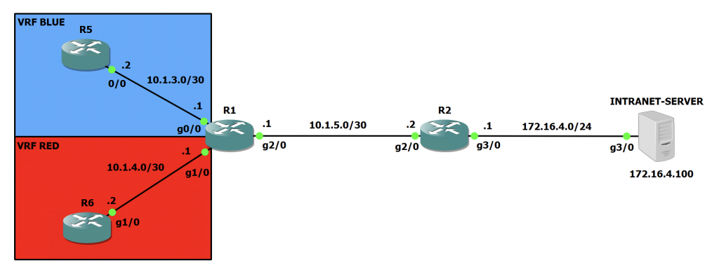
Here we can see two VRFs in use on R1. With R5 in the VRF called 'BLUE' and R6 in the VRF called 'RED'. We can also see on the far right hand side, there is the Intranet Server. This is just a Cisco IOS router so we can test pings once we are done. You can also see all the IP addresses on all of the interfaces too.
Within the network at the moment, all the IP addresses are configured and OSPF is running on both R1 and R2. This is just for the global routing table. No VRF specific OSPF instances are configured.
Lets check the routing tables on both R1 and R2:
R1#sh ip route | beg Gateway
Gateway of last resort is not set

      10.0.0.0/8 is variably subnetted, 2 subnets, 2 masks
C        10.1.5.0/30 is directly connected, GigabitEthernet2/0
L        10.1.5.1/32 is directly connected, GigabitEthernet2/0
      172.16.0.0/24 is subnetted, 1 subnets
O        172.16.4.0 [110/2] via 10.1.5.2, 00:04:44, GigabitEthernet2/0
R2#sh ip route | beg Gateway
Gateway of last resort is not set
10.0.0.0/8 is variably subnetted, 2 subnets, 2 masks
C 10.1.5.0/30 is directly connected, GigabitEthernet2/0
L 10.1.5.2/32 is directly connected, GigabitEthernet2/0
172.16.0.0/16 is variably subnetted, 2 subnets, 2 masks
C 172.16.4.0/24 is directly connected, GigabitEthernet3/0
L 172.16.4.1/32 is directly connected, GigabitEthernet3/0So, R1 can see the 172.16.4.0/24 network hanging off R2 as we expect. R2 doesn't have any OSPF routes as the network that R1 is advertising is directly connected on R2 (10.1.5.0/30).
Lets test that R1 can ping the Intranet Server from the global routing table:
R1#ping 172.16.4.100
Type escape sequence to abort.
Sending 5, 100-byte ICMP Echos to 172.16.4.100, timeout is 2 seconds:
!!!!!
Success rate is 100 percent (5/5), round-trip min/avg/max = 20/30/52 ms
From the above output, we can see that pings are succeeding. Now lets see what happens when we try and ping from the VRFs:
R1#ping vrf BLUE 172.16.4.100
Type escape sequence to abort.
Sending 5, 100-byte ICMP Echos to 172.16.4.100, timeout is 2 seconds:
.....
Success rate is 0 percent (0/5)
R1#ping vrf RED 172.16.4.100
Type escape sequence to abort.
Sending 5, 100-byte ICMP Echos to 172.16.4.100, timeout is 2 seconds:
.....
Success rate is 0 percent (0/5)
As we can see this isn't working. As the VRFs don't have a route to the 172.16.4.0/24 network. Lets fix that!
Lets take a snapshot of the routes in the VRFs first:
R1#sh ip route vrf BLUE | beg Gateway
Gateway of last resort is not set

      10.0.0.0/8 is variably subnetted, 2 subnets, 2 masks
C        10.1.3.0/30 is directly connected, GigabitEthernet0/0
L        10.1.3.1/32 is directly connected, GigabitEthernet0/0
R1#sh ip route vrf RED | beg Gateway
Gateway of last resort is not set

      10.0.0.0/8 is variably subnetted, 2 subnets, 2 masks
C        10.1.4.0/30 is directly connected, GigabitEthernet1/0
L        10.1.4.1/32 is directly connected, GigabitEthernet1/0
Firstly, we need to configure some some static routes to point the traffic at the correct next hop for each VRF:
R1(config)#ip route vrf BLUE 172.16.4.0 255.255.255.0 10.1.5.2 global
R1(config)#ip route vrf RED 172.16.4.0 255.255.255.0 10.1.5.2 global
Note in the above commands, we have to specify the VRF name, and the keyword 'global'. This indicates to the router that the next hop is in the global routing table and not within the VRF.
Lets have a look at the VRF routing tables now:
R1#sh ip route vrf BLUE | beg Gateway
Gateway of last resort is not set

      10.0.0.0/8 is variably subnetted, 2 subnets, 2 masks
C        10.1.3.0/30 is directly connected, GigabitEthernet0/0
L        10.1.3.1/32 is directly connected, GigabitEthernet0/0
      172.16.0.0/24 is subnetted, 1 subnets
S        172.16.4.0 [1/0] via 10.1.5.2
R1#sh ip route vrf RED | beg Gateway
Gateway of last resort is not set

      10.0.0.0/8 is variably subnetted, 2 subnets, 2 masks
C        10.1.4.0/30 is directly connected, GigabitEthernet1/0
L        10.1.4.1/32 is directly connected, GigabitEthernet1/0
      172.16.0.0/24 is subnetted, 1 subnets
S        172.16.4.0 [1/0] via 10.1.5.2
We can now see that we have a route to 172.16.4.0/24 in both VRF routing tables.
This will allow the traffic to flow from left to right in our topology. However, the return traffic will get stuck on R2 as it has no route to 10.1.3.0/30 or 10.1.4.0/30 in its global table.
Lets add two static routes on R2 to point those prefixes at the G2/0 interface on R1:
R2(config)#ip route 10.1.3.0 255.255.255.252 10.1.5.1
R2(config)#ip route 10.1.4.0 255.255.255.252 10.1.5.1
R2(config)#do sh ip route | beg Gateway
Gateway of last resort is not set

      10.0.0.0/8 is variably subnetted, 4 subnets, 2 masks
S        10.1.3.0/30 [1/0] via 10.1.5.1
S        10.1.4.0/30 [1/0] via 10.1.5.1
C        10.1.5.0/30 is directly connected, GigabitEthernet2/0
L        10.1.5.2/32 is directly connected, GigabitEthernet2/0
      172.16.0.0/16 is variably subnetted, 2 subnets, 2 masks
C        172.16.4.0/24 is directly connected, GigabitEthernet3/0
L        172.16.4.1/32 is directly connected, GigabitEthernet3/0
At this point, we will still not have full connectivity. This is because on R1 the interfaces in the VRFs will not show in the global routing table. Even though the interfaces are on the router, we need to again configure some static routes to tell the global table where 10.1.3.0/30 and 10.1.4.0/30 are.
Finally, let's add two static routes on R1 pointing the traffic to the designated interfaces. We have to specify the interfaces here, as the global table can't see the VRF subnets:
R1(config)#ip route 10.1.3.0 255.255.255.252 GigabitEthernet0/0
R1(config)#ip route 10.1.4.0 255.255.255.252 GigabitEthernet1/0
R1(config)#do sh ip route | beg Gateway
Gateway of last resort is not set

      10.0.0.0/8 is variably subnetted, 4 subnets, 2 masks
S        10.1.3.0/30 is directly connected, GigabitEthernet0/0
S        10.1.4.0/30 is directly connected, GigabitEthernet1/0
C        10.1.5.0/30 is directly connected, GigabitEthernet2/0
L        10.1.5.1/32 is directly connected, GigabitEthernet2/0
      172.16.0.0/24 is subnetted, 1 subnets
O        172.16.4.0 [110/2] via 10.1.5.2, 01:32:11, GigabitEthernet2/0
Now lets test those pings again from R1 initally:
R1#ping vrf BLUE 172.16.4.100
Type escape sequence to abort.
Sending 5, 100-byte ICMP Echos to 172.16.4.100, timeout is 2 seconds:
!!!!!
Success rate is 100 percent (5/5), round-trip min/avg/max = 20/24/36 ms
R1#ping vrf RED 172.16.4.100
Type escape sequence to abort.
Sending 5, 100-byte ICMP Echos to 172.16.4.100, timeout is 2 seconds:
!!!!!
Success rate is 100 percent (5/5), round-trip min/avg/max = 20/20/24 ms
As we can see, those pings are working from R1! Lets test on R5 and R6:
Note: R5 has a static default route pointing at 10.1.3.1 and R6 has one pointing at 10.1.4.1.
R5#ping 172.16.4.100
Type escape sequence to abort.
Sending 5, 100-byte ICMP Echos to 172.16.4.100, timeout is 2 seconds:
!!!!!
Success rate is 100 percent (5/5), round-trip min/avg/max = 52/58/68 ms
R5#trace 172.16.4.100
Type escape sequence to abort.
Tracing the route to 172.16.4.100
VRF info: (vrf in name/id, vrf out name/id)
  1 10.1.3.1 24 msec 12 msec 20 msec
  2 10.1.5.2 28 msec 28 msec 28 msec
  3 172.16.4.100 52 msec 40 msec 32 msec
R6#ping 172.16.4.100
Type escape sequence to abort.
Sending 5, 100-byte ICMP Echos to 172.16.4.100, timeout is 2 seconds:
!!!!!
Success rate is 100 percent (5/5), round-trip min/avg/max = 28/55/116 ms
R6#trace 172.16.4.100
Type escape sequence to abort.
Tracing the route to 172.16.4.100
VRF info: (vrf in name/id, vrf out name/id)
1 10.1.4.1 16 msec 12 msec 8 msec
2 10.1.5.2 24 msec 20 msec 20 msec
3 172.16.4.100 32 msec 28 msec 32 msecWe now have connectivity out of the VRF and to the Intranet Server. We will also check to make sure that the VRFs are still unable to communicate with each other:
R5#ping 10.1.4.2
Type escape sequence to abort.
Sending 5, 100-byte ICMP Echos to 10.1.3.2, timeout is 2 seconds:
UUUUU
Success rate is 0 percent (0/5)
R6#ping 10.1.3.2
Type escape sequence to abort.
Sending 5, 100-byte ICMP Echos to 10.1.3.2, timeout is 2 seconds:
UUUUU
Success rate is 0 percent (0/5)The VRFs are still unable to communicate which is what we want.

0 Comments