In this part we are going to look at the L3VNI config to get the hosts in the two vlans talking to each other.
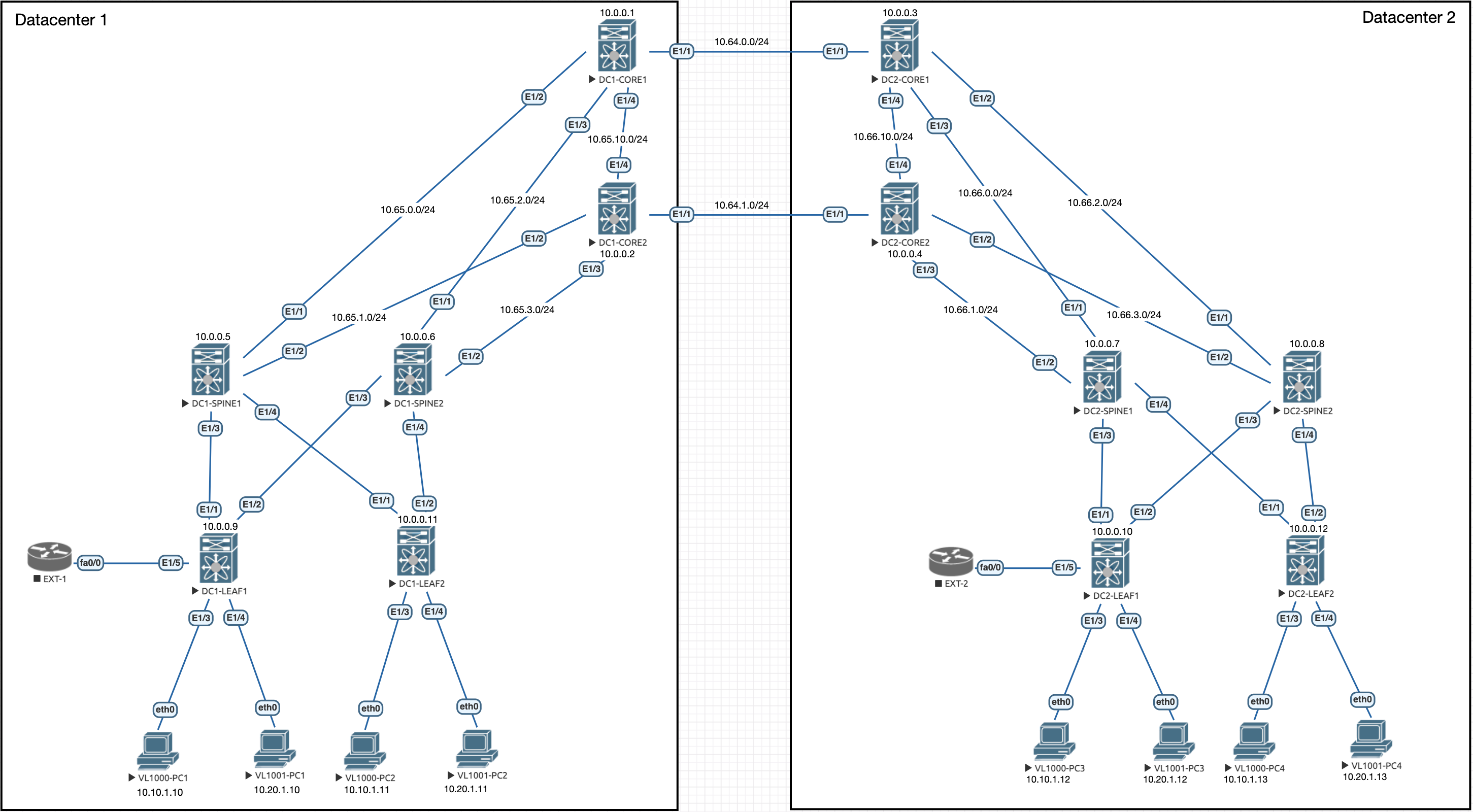
Lets remind ourselves of the topology:

All of the configuration below is for the Leaves in the topology. There is some setup on the Core switches but that is right at the end.
Vlan Configuration
Firstly, we need to configure a L3VNI vlan for the routing, this configuration is for the leaves:
vlan 999
  vn-segment 900101
The vn-segment above should match the vni configured in the last part on the VRF created.
SVI and NVE Configuration
The vlan needs an SVI and also needs to be added into the NVE logical interface:
interface Vlan999
  no shutdown
  vrf member overlay-900101
  ip forward

interface nve1
  member vni 900101 associate-vrf
BGP Additional Configuration
We also need to add some additional BGP configuration to the leaves:
DC1:
router bgp 100
  vrf overlay-900101
    log-neighbor-changes
    address-family ipv4 unicast
      network 10.10.1.0/24
      network 10.20.1.0/24
DC2:
router bgp 200
  vrf overlay-900101
    log-neighbor-changes
    address-family ipv4 unicast
      network 10.10.1.0/24
      network 10.20.1.0/24
Making sure that if you have more subnets to add them with the network command. You could also do some redistribution if you prefer, as long as the routes are advertised into BGP.
Verification
At this point, we should be able to verify the config is working by pinging a server in vlan1001 from a server in vlan1000:
VPCS> show ip

NAME        : VPCS[1]
IP/MASK     : 10.10.1.10/24
GATEWAY     : 10.10.1.254
DNS         :
MAC         : 00:50:79:66:68:01
LPORT       : 20000
RHOST:PORT  : 127.0.0.1:30000
MTU         : 1500

VPCS> ping 10.20.1.11

84 bytes from 10.20.1.11 icmp_seq=1 ttl=62 time=67.434 ms
84 bytes from 10.20.1.11 icmp_seq=2 ttl=62 time=9.840 ms
84 bytes from 10.20.1.11 icmp_seq=3 ttl=62 time=13.897 ms
84 bytes from 10.20.1.11 icmp_seq=4 ttl=62 time=9.552 ms
84 bytes from 10.20.1.11 icmp_seq=5 ttl=62 time=8.474 ms

VPCS> trace 10.20.1.11
trace to 10.20.1.11, 8 hops max, press Ctrl+C to stop
 1   10.10.1.254   2.900 ms  1.065 ms  1.076 ms
 2   10.10.1.254   10.530 ms  5.860 ms  5.361 ms
 3   10.20.1.11   7.010 ms
As you can see from the above, the ping from a server in vlan 1000 to a server in vlan 1001 works and we can also see the traceroute showing the path from server to server. The reason for the double gateway hops are due to the distributed anycast gateway hitting the gateway on the local VTEP and then the remote VTEP.
Core Configuration
That was still within the local DC, we need some extra configuration on the Core switches to be able to do this between the DCs.
We need to create the l2 vlan for the l3vni:
vlan 999
  vn-segment 900101
We also need to assign the VRF created in the previous part to the NVE interface:
interface nve1
  member vni 900101 associate-vrf
Finally, add the SVI:
interface Vlan999
  no shutdown
  vrf member overlay-900101
  ip forward
Now we will have L3 connectivity between the DCs:
VPCS> show ip

NAME        : VPCS[1]
IP/MASK     : 10.10.1.10/24
GATEWAY     : 10.10.1.254
DNS         :
MAC         : 00:50:79:66:68:01
LPORT       : 20000
RHOST:PORT  : 127.0.0.1:30000
MTU         : 1500

VPCS> ping 10.20.1.12

84 bytes from 10.20.1.12 icmp_seq=1 ttl=60 time=30.245 ms
84 bytes from 10.20.1.12 icmp_seq=2 ttl=60 time=17.150 ms
84 bytes from 10.20.1.12 icmp_seq=3 ttl=60 time=16.159 ms
84 bytes from 10.20.1.12 icmp_seq=4 ttl=60 time=23.431 ms
84 bytes from 10.20.1.12 icmp_seq=5 ttl=60 time=22.100 ms
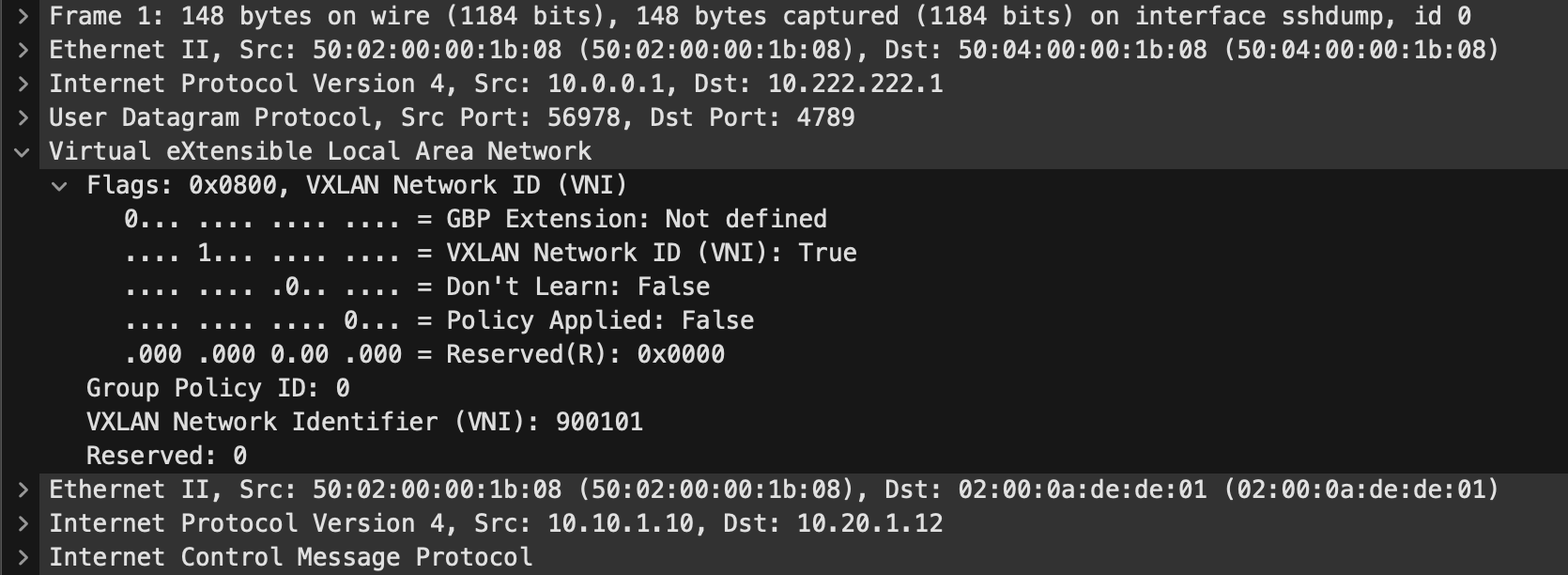
For fun, lets take a quick packet capture on the DCIs and see the Ping traffic going across!

In the above we can see the ICMP request going across the DCI for the other PC. The VXLAN header is expanded and we can see the ID of the L3VNI because this is inter-vni traffic. If the traffic was between two PCs on the same vni, the ID would be the L2VNI.
Now we have internal communications within the fabric between VNIs and DCs. Next we will look at layering on another tenant vrf to show a multi tenant design.

0 Comments