In this part we are going to look at the L3VNI config to get the hosts in the two vlans talking to each other.
Lets remind ourselves of the topology:
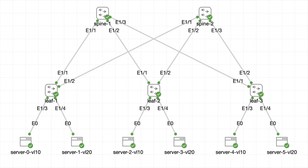
All of the configuration below is for the Leaves in the topology.
Vlan Configuration
Firstly, we need to configure a L3VNI vlan for the routing, this configuration is for the leaves:
vlan 999
  vn-segment 100999
VRF Configuration
We also need a tenant VRF to be configured which will house the overlay routing:
vrf context OVERLAY-TENANT1
  vni 100999
  rd auto
  address-family ipv4 unicast
    route-target both auto
    route-target both auto evpn
This configuration also brings in the EVPN information too.
SVI and NVE Configuration
The vlan needs an SVI and also needs to be added into the NVE logical interface:
interface Vlan999
  no shutdown
  vrf member OVERLAY-TENANT1
  ip forward

interface nve1
  member vni 100999 associate-vrf
You also need to add the SVIs with the anycast gateways to the VRF too:
interface Vlan10
  vrf member OVERLAY-TENANT1
  ip address 10.10.1.254/24
  fabric forwarding mode anycast-gateway

interface Vlan20
  vrf member OVERLAY-TENANT1
  ip address 10.20.1.254/24
  fabric forwarding mode anycast-gateway
Making sure to add the Layer 3 information back to them after applying the VRF.
BGP Additional Configuration
We also need to add some additional BGP configuration to the leaves:
router bgp 64500
  vrf OVERLAY-TENANT1
    log-neighbor-changes
    address-family ipv4 unicast
      network 10.10.1.0/24
      network 10.20.1.0/24
Making sure that if you have more subnets to add them with the network command. You could also do some redistribution if you prefer, as long as the routes are advertised into BGP.
Verification
At this point, we should be able to verify the config is working:
server-0-vl10:~$ ping 10.20.1.2
PING 10.20.1.2 (10.20.1.2): 56 data bytes
64 bytes from 10.20.1.2: seq=0 ttl=42 time=16.382 ms
64 bytes from 10.20.1.2: seq=1 ttl=42 time=9.942 ms
64 bytes from 10.20.1.2: seq=2 ttl=42 time=9.304 ms
64 bytes from 10.20.1.2: seq=3 ttl=42 time=8.816 ms
64 bytes from 10.20.1.2: seq=4 ttl=42 time=11.501 ms
^C
--- 10.20.1.2 ping statistics ---
5 packets transmitted, 5 packets received, 0% packet loss
round-trip min/avg/max = 8.816/11.189/16.382 ms
server-0-vl10:~$ traceroute 10.20.1.2
traceroute to 10.20.1.2 (10.20.1.2), 30 hops max, 46 byte packets
 1  10.10.1.254 (10.10.1.254)  2.087 ms  1.494 ms  1.504 ms
 2  10.10.1.254 (10.10.1.254)  8.518 ms  9.001 ms  6.595 ms
 3  10.20.1.2 (10.20.1.2)  9.978 ms  28.256 ms  13.771 ms
As you can see from the above, the ping from a server in vlan 10 to a server in vlan 20 works and we can also see the traceroute showing the path from server-0 to server-3. The reason for the double gateway hops are due to the distributed anycast gateway hitting the gateway on the local VTEP and then the remote VTEP.
Now we have internal communications within the fabric between VNIs. Next we will look at layering on another tenant vrf to show a multi tenant design.

0 Comments