In this series of guides, we will be completing the setup of a VXLAN fabric, with the leaf switches being in vPC pairs, this creates some interesting config additions we need to consider. In this part, we will look at the topology and setup the vPC domains.
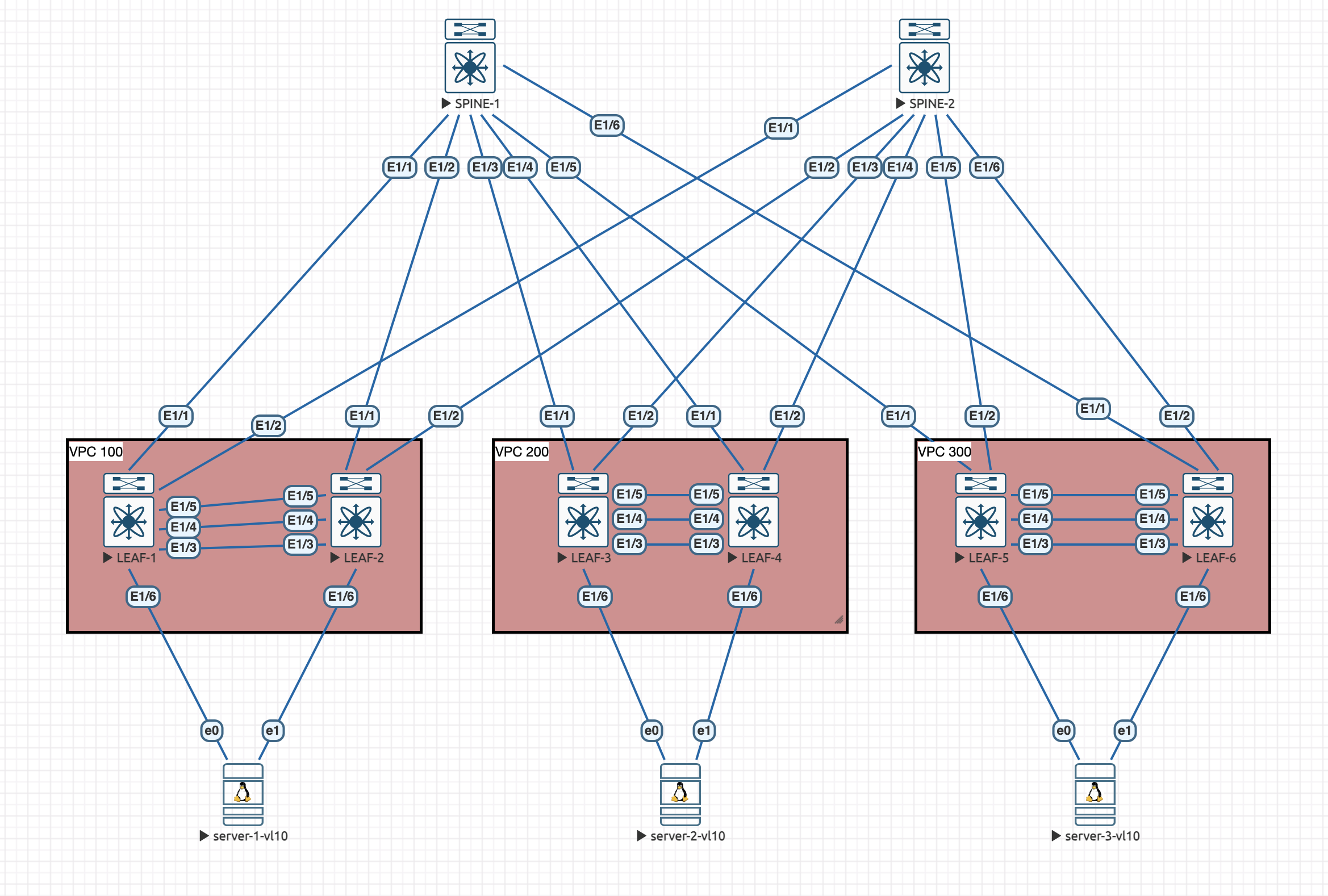
Here is the topology we will be working with:

The switches are all Nexus C9300v running NX-OS version 10.3(5).
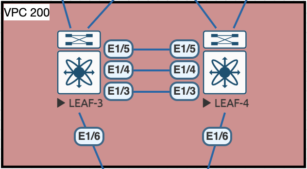
Homing in on one of the vPC domains, lets show the different type of interfaces we have:

Eth1/3 and Eth1/4 will make up port-channel1 and will be our vPC peer-link, then Eth1/5 will be a layer 3 link for the peer keepalive, in its own VRF. If this terminology isn't familiar to you, I do have a set of posts on vPC which goes through all this in more detail.
vPC Configuration
The vPC configuration is only relevant for the leaves, no configuration is required for the spine switches as they will not be in vPC pairs.
Firstly we should enable all the features we need for the vPC configuration on all switches:
feature lacp
feature vpc
I am going to use the following IPs for the peer keepalive links:
- VPC Domain 100
- LEAF-1 - 172.16.0.0/31
- LEAF-2 - 172.16.0.1/31
- VPC Domain 200
- LEAF-3 - 172.16.0.2/31
- LEAF-4 - 172.16.0.3/31
- VPC Domain 300
- LEAF-3 - 172.16.0.4/31
- LEAF-4 - 172.16.0.5/31
This is the configuration for the Keepalive VRF and interface per switch, swapping the IP for each switch with its denoted IP:
vrf context PEERKEEPALIVE
exit
int Eth1/5
  no switchport
  no shutdown
  vrf member PEERKEEPALIVE
  ip address 172.16.0.x/31
Now we need to configure the actual VPC domain, and set the parameters for the switches to talk to one another:
LEAF-1:
vpc domain 100
  peer-switch
  peer-keepalive destination 172.16.0.1 source 172.16.0.0 vrf PEERKEEPALIVE
  peer-gateway
  ip arp synchronize
LEAF-2:
vpc domain 100
  peer-switch
  peer-keepalive destination 172.16.0.0 source 172.16.0.1 vrf PEERKEEPALIVE
  peer-gateway
  ip arp synchronize
LEAF-3:
vpc domain 200
  peer-switch
  peer-keepalive destination 172.16.0.3 source 172.16.0.2 vrf PEERKEEPALIVE
  peer-gateway
  ip arp synchronize
LEAF-4:
vpc domain 200
  peer-switch
  peer-keepalive destination 172.16.0.2 source 172.16.0.3 vrf PEERKEEPALIVE
  peer-gateway
  ip arp synchronize
LEAF-5:
vpc domain 300
  peer-switch
  peer-keepalive destination 172.16.0.5 source 172.16.0.4 vrf PEERKEEPALIVE
  peer-gateway
  ip arp synchronize
LEAF-6:
vpc domain 300
  peer-switch
  peer-keepalive destination 172.16.0.4 source 172.16.0.5 vrf PEERKEEPALIVE
  peer-gateway
  ip arp synchronize
On all of the leaves we should see that the peer shows as alive:
LEAF-1# show vpc brief | inc keep-alive
vPC keep-alive status             : peer is alive
Finally, we need to configure the port-channel for the peer-link. This config is the same for all leaves:
interface Eth1/3-4
  channel-group 1 mode active
  no shutdown
interface port-channel1
  switchport mode trunk
  spanning-tree port type network
  vpc peer-link
The vPC should now be fully formed:
LEAF-1# show vpc brief
Legend:
                (*) - local vPC is down, forwarding via vPC peer-link

vPC domain id                     : 100
Peer status                       : peer adjacency formed ok
vPC keep-alive status             : peer is alive
Configuration consistency status  : success
Per-vlan consistency status       : success
Type-2 consistency status         : success
vPC role                          : primary
Number of vPCs configured         : 0
Peer Gateway                      : Enabled
Dual-active excluded VLANs        : -
Graceful Consistency Check        : Enabled
Auto-recovery status              : Disabled
Delay-restore status              : Timer is on.(timeout = 30s, 13s left)
Delay-restore SVI status          : Timer is off.(timeout = 10s)
Delay-restore Orphan-port status  : Timer is off.(timeout = 0s)
Operational Layer3 Peer-router    : Disabled
Virtual-peerlink mode             : Disabled

vPC Peer-link status
---------------------------------------------------------------------
id    Port   Status Active vlans
--    ----   ------ -------------------------------------------------
1     Po1    up     1
That command should show a similar output on all switches, the parts we are looking out for are:
peer adjacency formed ok and peer is alive. Also the success status of the consistency checks.
The last thing to do is configure the vPC member interfaces down to our servers. Again, this configuration is the same on all switches:
interface Eth1/6
  channel-group 2 mode active
  no shutdown
interface port-channel2
  vpc 2
I have configured the linux servers connected to the leaves with a netplan LACP config that should work with the switches, we can test the vPC comes up on the Nexus side:
LEAF-5# show vpc 2

vPC status
----------------------------------------------------------------------------
Id    Port          Status Consistency Reason                Active vlans
--    ------------  ------ ----------- ------                ---------------
2     Po2           up     success     success               1
That looks good, the status is up and the configuration is consistent between vPC members. The Active vlans part is OK for the moment, we will be adding the correct vlan later on.
So, thats the vPC domains setup. In the next part we will look at the underlay setup with OSPF and some multicast!

0 Comments