In the last part, we got route leaking in tenant VRFs working, in this part, we will look at giving the VRFs a way out of the Fabric!
We have added some new devices to the topology:
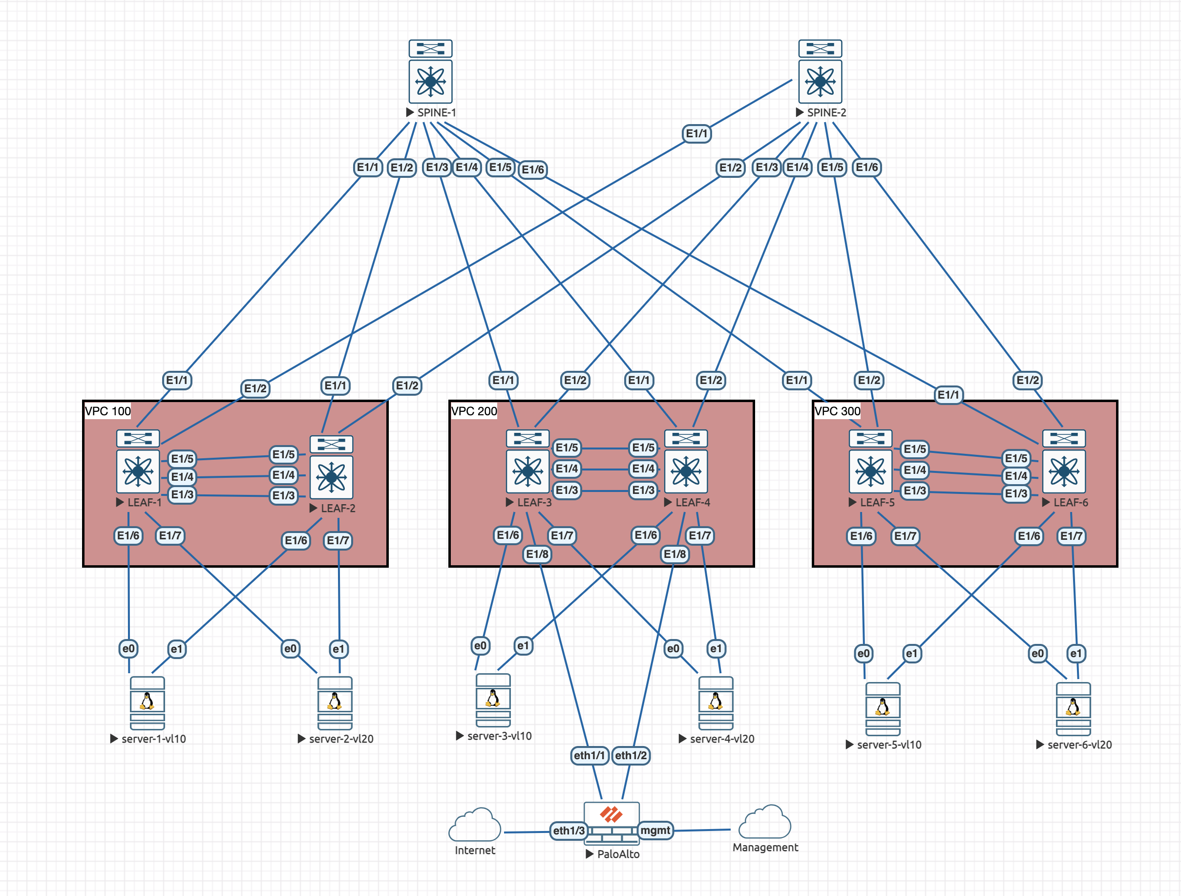
We can see the addition of the palo alto firewall that is connected to the border leaf. We have to connect these type of external devices to the border leaf because it has the default route pointing towards it for simplicity.
We currently have the Vlan10 and Vlan20 devices split into two Tenant VRFs. In order to allow both tenants to able to access the shared resources (on the Palo Alto Firewall), we will need another VRF for the shared routes. If you were breaking out local Tenant VRFs, then you would use that Tenant's VRF.
Underlying PaloAlto Connection
The PaloAlto firewall is configured with two interfaces connected to the fabric and one connected out to the real internet. Connected to the fabric, this is a vPC configured as a Trunk with a single vlan allowed:
interface Ethernet1/8
  no shutdown
  channel-group 4 mode active

interface port-channel4
  switchport mode trunk
  switchport trunk allowed vlan 3260
  vpc 4
We do need to create an SVI on each border leaf for this Vlan. However, we can't do it yet because it needs to be in the new VRF.
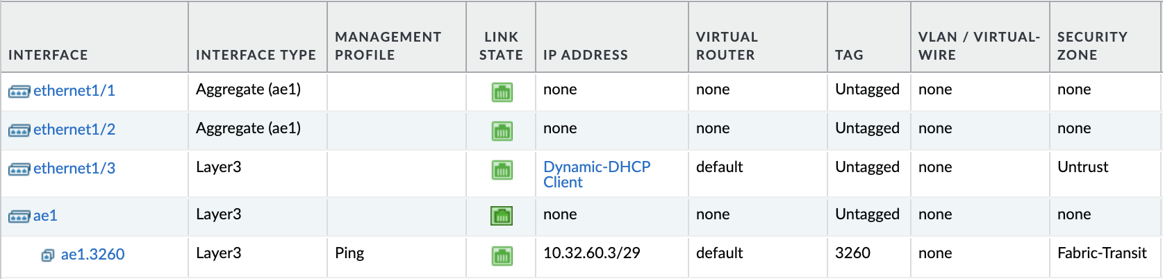
On the PaloAlto side, this is how the interfaces are setup:
VRF Configuration
So, we only need to create the VRF and leak the routes on LEAF-3 and LEAF-4:
vrf context external
  vni 100555
  rd auto
  address-family ipv4 unicast
    route-target both auto
    route-target both auto evpn
    route-target import 64500:100998
    route-target import 64500:100998 evpn
    route-target import 64500:100999
    route-target import 64500:100999 evpn
Before we continue, lets quickly go over what this config should do. It creates a new VRF called external and assigns a VNI (required later). Within the address family, we auto assign a RT, which will be 64500:100555 from the VNI we set. We then import the routes from the other Tenant VRFs so that we have routes back, note that we also have the EVPN keyword so that we bring the EVPN /32 routes in too, reverse routing will fail without the specific routes.
We also need to amend the VRF configuration for the existing ones on LEAF-3 and LEAF-4:
vrf context OVERLAY-TENANT1
  address-family ipv4 unicast
    route-target import 64500:100555

vrf context OVERLAY-TENANT2
  address-family ipv4 unicast
    route-target import 64500:100555
This config will import routes from the external VRF.
Lets do some quick verification:
LEAF-3# show ip route vrf external
IP Route Table for VRF "external"

10.1.0.0/16, ubest/mbest: 1/0
    *via Null0, [220/0], 00:00:55, bgp-64500, discard, tag 64500
10.1.1.0/24, ubest/mbest: 1/0, attached
    *via 10.1.1.254%OVERLAY-TENANT1, Vlan10, [20/0], 00:00:55, bgp-64500, external, tag 64500
10.2.0.0/16, ubest/mbest: 1/0
    *via Null0, [220/0], 00:00:55, bgp-64500, discard, tag 64500
10.2.1.0/24, ubest/mbest: 1/0, attached
    *via 10.2.1.254%OVERLAY-TENANT2, Vlan20, [20/0], 00:00:55, bgp-64500, external, tag 64500
LEAF-3# show ip route vrf OVERLAY-TENANT1
IP Route Table for VRF "OVERLAY-TENANT1"

10.1.0.0/16, ubest/mbest: 1/0
    *via Null0, [220/0], 00:29:06, bgp-64500, discard, tag 64500
10.1.1.0/24, ubest/mbest: 1/0, attached
    *via 10.1.1.254, Vlan10, [0/0], 00:31:57, direct
10.1.1.1/32, ubest/mbest: 1/0
    *via 10.0.1.101%default, [200/0], 00:35:26, bgp-64500, internal, tag 64500, segid: 100999 tunnelid: 0xa000165 encap: VXLAN

10.1.1.2/32, ubest/mbest: 1/0, attached
    *via 10.1.1.2, Vlan10, [190/0], 00:24:24, hmm
10.1.1.254/32, ubest/mbest: 1/0, attached
    *via 10.1.1.254, Vlan10, [0/0], 00:31:57, local
10.2.0.0/16, ubest/mbest: 1/0
    *via Null0, [220/0], 00:38:19, bgp-64500, discard, tag 64500
10.2.1.0/24, ubest/mbest: 1/0, attached
    *via 10.2.1.254%OVERLAY-TENANT2, Vlan20, [20/0], 00:31:55, bgp-64500, external, tag 64500
10.2.1.1/32, ubest/mbest: 1/0
    *via 10.0.1.101%default, [200/0], 00:29:32, bgp-64500, internal, tag 64500, segid: 100998 (Asymmetric) tunnelid: 0xa000165 encap: VXLAN
LEAF-3# show ip route vrf OVERLAY-TENANT2
IP Route Table for VRF "OVERLAY-TENANT2"
10.1.0.0/16, ubest/mbest: 1/0
*via Null0, [220/0], 00:38:44, bgp-64500, discard, tag 64500
10.1.1.0/24, ubest/mbest: 1/0, attached
*via 10.1.1.254%OVERLAY-TENANT1, Vlan10, [20/0], 00:32:20, bgp-64500, external, tag 64500
10.1.1.1/32, ubest/mbest: 1/0
*via 10.0.1.101%default, [200/0], 00:35:51, bgp-64500, internal, tag 64500, segid: 100999 (Asymmetric) tunnelid: 0xa000165 encap: VXLAN
10.2.0.0/16, ubest/mbest: 1/0
*via Null0, [220/0], 00:29:31, bgp-64500, discard, tag 64500
10.2.1.0/24, ubest/mbest: 1/0, attached
*via 10.2.1.254, Vlan20, [0/0], 00:32:22, direct
10.2.1.1/32, ubest/mbest: 1/0
*via 10.0.1.101%default, [200/0], 00:29:57, bgp-64500, internal, tag 64500, segid: 100998 tunnelid: 0xa000165 encap: VXLAN
10.2.1.2/32, ubest/mbest: 1/0, attached
*via 10.2.1.2, Vlan20, [190/0], 00:28:37, hmm
10.2.1.254/32, ubest/mbest: 1/0, attached
*via 10.2.1.254, Vlan20, [0/0], 00:32:22, localWe can see that the external VRF contains the /24 routes from each Tenant VRF and the summary /16 routes, however, it doesn't contain any of the /32 VXLAN routes. This is because we haven't completed the L3VNI setup for it yet.
L3VNI Setup
Now we have completed the VRF config, lets complete the L3VNI config on the border leaves:
vlan 555
  vn-segment 100555

interface Vlan555
  no shutdown
  vrf member external
  ip forward

interface nve1
  member vni 100555 associate-vrf
Now, we should see the VXLAN routes in the external VRF:
LEAF-3# show ip route vrf external
IP Route Table for VRF "external"

10.1.0.0/16, ubest/mbest: 1/0
    *via Null0, [220/0], 00:00:06, bgp-64500, discard, tag 64500
10.1.1.0/24, ubest/mbest: 1/0, attached
    *via 10.1.1.254%OVERLAY-TENANT1, Vlan10, [20/0], 00:02:50, bgp-64500, external, tag 64500
10.1.1.1/32, ubest/mbest: 1/0
    *via 10.0.1.101%default, [200/0], 00:00:06, bgp-64500, internal, tag 64500, segid: 100999 (Asymmetric) tunnelid: 0xa000165 encap: VXLAN

10.2.0.0/16, ubest/mbest: 1/0
    *via Null0, [220/0], 00:00:06, bgp-64500, discard, tag 64500
10.2.1.0/24, ubest/mbest: 1/0, attached
    *via 10.2.1.254%OVERLAY-TENANT2, Vlan20, [20/0], 00:02:50, bgp-64500, external, tag 64500
10.2.1.1/32, ubest/mbest: 1/0
    *via 10.0.1.101%default, [200/0], 00:00:06, bgp-64500, internal, tag 64500, segid: 100998 (Asymmetric) tunnelid: 0xa000165 encap: VXLAN
Interface Config
Now the VRF is configured we need to configure the SVI on the border leaves:
LEAF-3:
interface Vlan3260
  no shutdown
  vrf member external
  no ip redirects
  ip address 10.32.60.1/29
LEAF-4:
interface Vlan3260
  no shutdown
  vrf member external
  no ip redirects
  ip address 10.32.60.2/29
We should be able to ping the leaves from the firewall now:
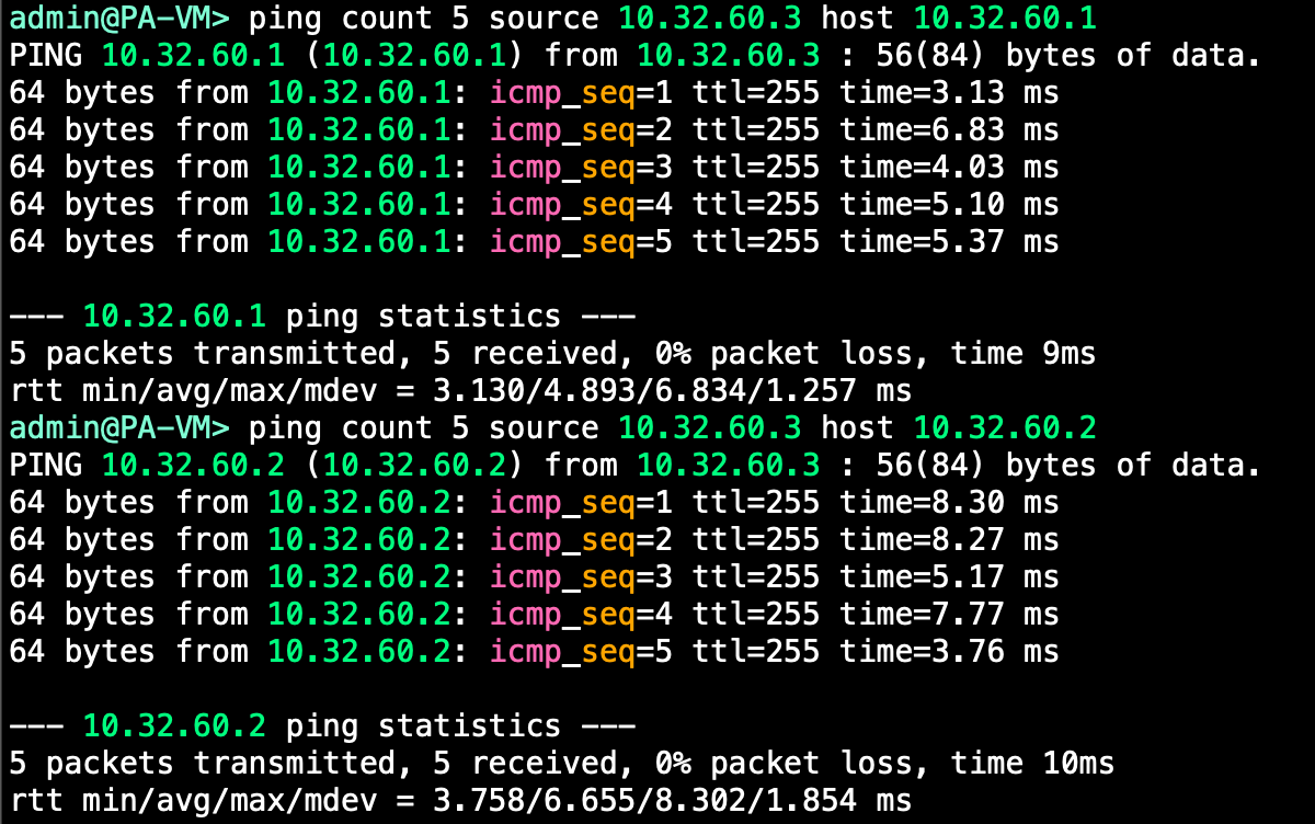
Perfect, we have connectivity between the Firewall and the Fabric.
BGP Peerings
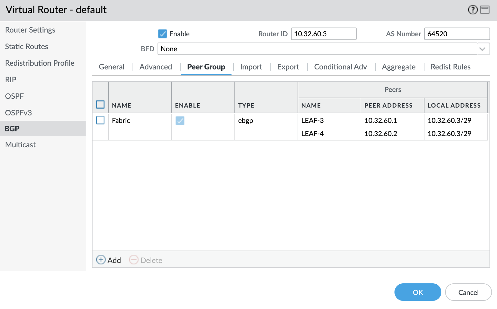
Now the interfaces are configured, we need to add a BGP peerings on the border leaves.
The fabric will stay as asn64500 and the firewall is asn64520. So this will be an eBGP peering:
router bgp 64500
  vrf external
  neighbor 10.32.60.3 remote-as 64520
    address-family ipv4 unicast
  exit
exit
We also need to configure a peering to each Border Leaf on the Firewall:
We should see the neighborships come up. We aren't sending any routes form the Firewall yet, but we should see some routes on the Firewall from the fabric:
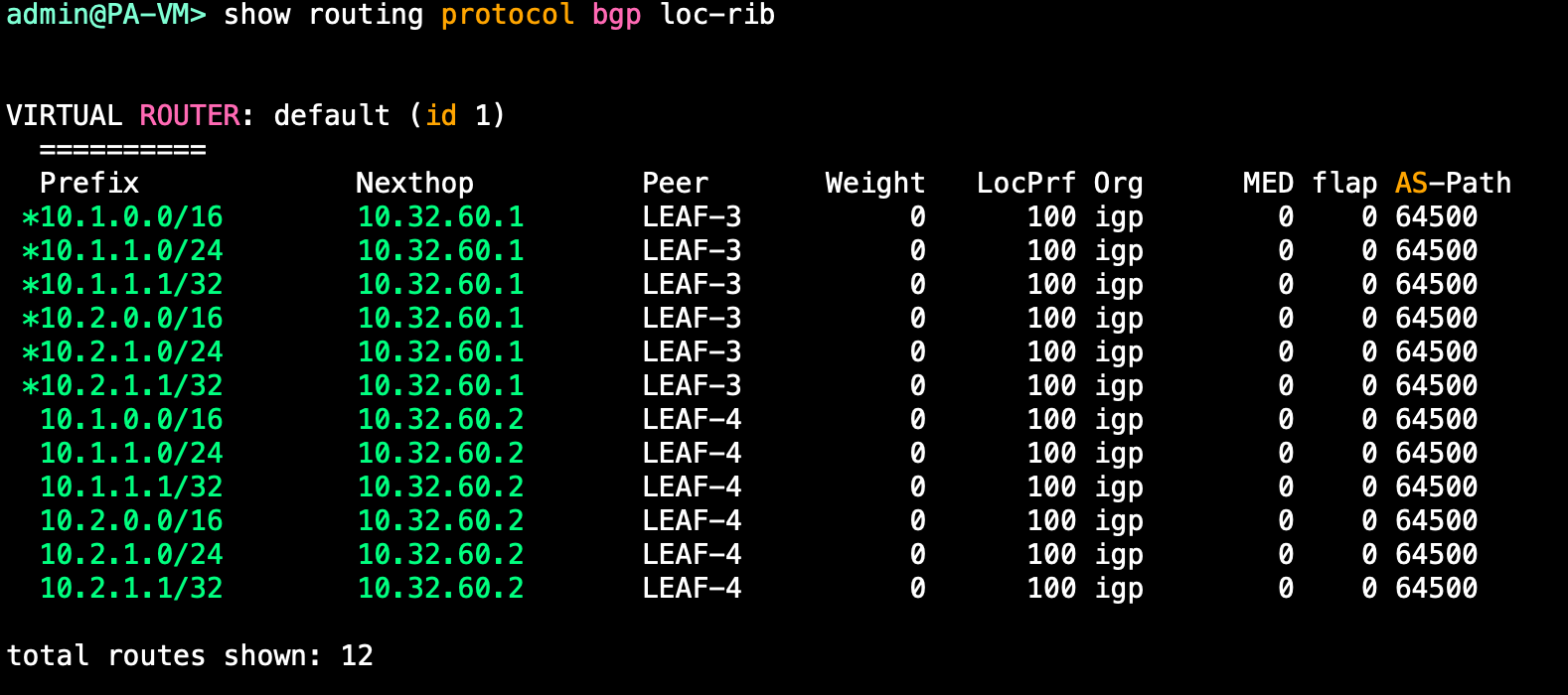
And we do! However, it looks like we don't have ECMP enabled, lets fix that!
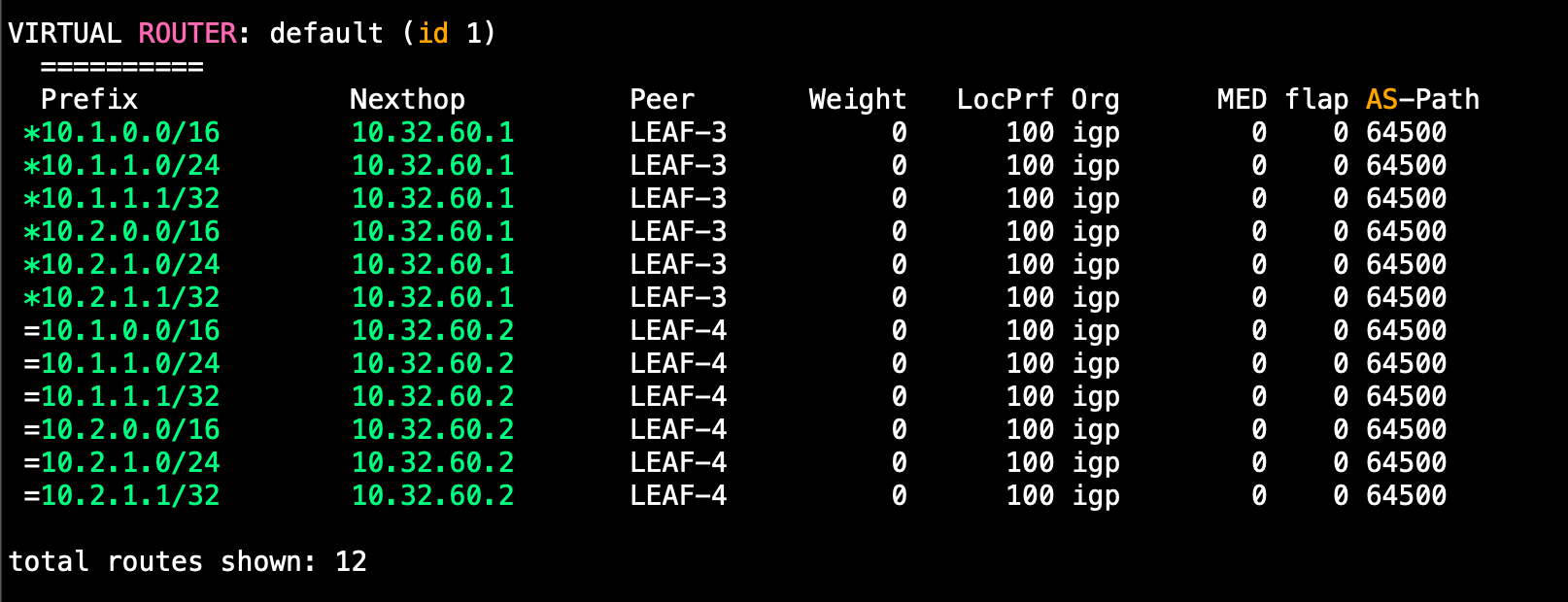
There we go, now we have ECMP enabled so the firewall will forward to either border leaf.
Although, we can see that we are getting a lot of /32s from the fabric. Lets filter these out from being sent:
ip prefix-list non-host-routes seq 5 permit 0.0.0.0/0 le 31
route-map deny-host-routes permit 10
match ip address prefix-list non-host-routes
router bgp 64500
vrf external
neighbor 10.32.60.3
address-family ipv4 unicast
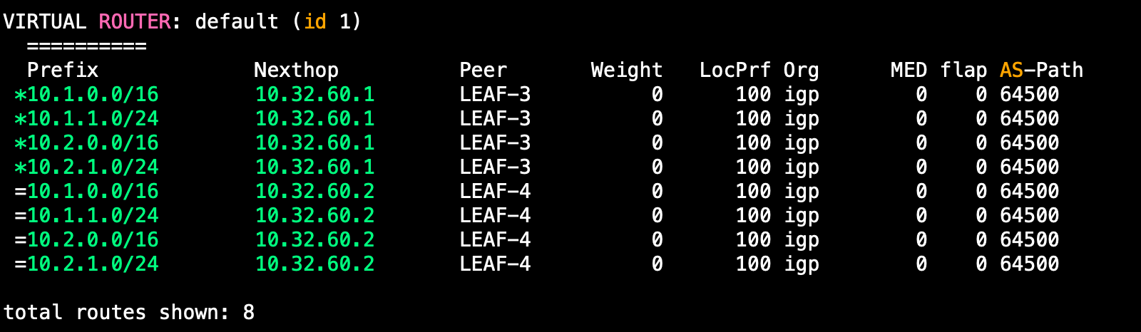
route-map deny-host-routes outNow we cannot see the host routes:
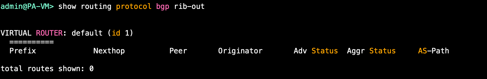
Last thing we need to do on BGP is advertise a default route from the Firewall into the fabric.
Before:
After:
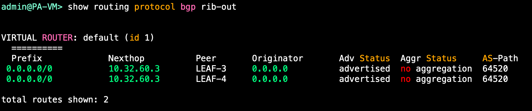
We should see these routes on the Border leaves in multiple VRFs:
LEAF-3# show ip route 0.0.0.0/0 vrf all
IP Route Table for VRF "OVERLAY-TENANT1"

0.0.0.0/0, ubest/mbest: 1/0
    *via 10.32.60.3%external, [20/0], 00:03:31, bgp-64500, external, tag 64520
IP Route Table for VRF "OVERLAY-TENANT2"

0.0.0.0/0, ubest/mbest: 1/0
    *via 10.32.60.3%external, [20/0], 00:03:31, bgp-64500, external, tag 64520
IP Route Table for VRF "external"

0.0.0.0/0, ubest/mbest: 1/0
    *via 10.32.60.3, [20/0], 00:03:31, bgp-64500, external, tag 64520
LEAF-4# show ip route 0.0.0.0/0 vrf all
IP Route Table for VRF "OVERLAY-TENANT1"
0.0.0.0/0, ubest/mbest: 1/0
*via 10.32.60.3%external, [20/0], 00:02:23, bgp-64500, external, tag 64520
IP Route Table for VRF "OVERLAY-TENANT2"
0.0.0.0/0, ubest/mbest: 1/0
*via 10.32.60.3%external, [20/0], 00:02:23, bgp-64500, external, tag 64520
IP Route Table for VRF "external"
0.0.0.0/0, ubest/mbest: 1/0
*via 10.32.60.3, [20/0], 00:02:23, bgp-64500, external, tag 64520Perfect, that shows in the external VRF and also the tenant VRFs. Now lets see what we see on the other non-border leaves in the tenant VRFs:
LEAF-1# show ip route 0.0.0.0/0 vrf all
IP Route Table for VRF "OVERLAY-TENANT1"

Route not found
IP Route Table for VRF "OVERLAY-TENANT2"

Route not found
Hmm, no route there. This is the same on all of the non-border leaves.
Now, if you have read the other posts I have done on external fabric connectivity in VXLAN, you likely know what is happening here. We need to tell the border leaves that they are allowed to advertise this subnet as it has come from another 'VPN' essentially. This being the external VRF.
We need to put the following configuration on the Border Leaves:
vrf context OVERLAY-TENANT1
  address-family ipv4 unicast
    import vrf advertise-vpn
vrf context OVERLAY-TENANT2
  address-family ipv4 unicast
    import vrf advertise-vpn
Now if we check back on a normal leaf, we should see the the routes now:
LEAF-1# show ip route 0.0.0.0/0 vrf all
IP Route Table for VRF "OVERLAY-TENANT1"

0.0.0.0/0, ubest/mbest: 2/0
    *via 10.0.1.3%default, [200/0], 00:59:55, bgp-64500, internal, tag 64520, segid: 100999 tunnelid: 0xa000103 encap: VXLAN
    *via 10.0.1.4%default, [200/0], 00:59:40, bgp-64500, internal, tag 64520, segid: 100999 tunnelid: 0xa000104 encap: VXLAN

IP Route Table for VRF "OVERLAY-TENANT2"

0.0.0.0/0, ubest/mbest: 2/0
    *via 10.0.1.3%default, [200/0], 00:00:19, bgp-64500, internal, tag 64520, segid: 100998 tunnelid: 0xa000103 encap: VXLAN
    *via 10.0.1.4%default, [200/0], 00:00:19, bgp-64500, internal, tag 64520, segid: 100998 tunnelid: 0xa000104 encap: VXLAN
Now we have the routes in the tenant VRFs and we can see that the next hops are via the border leaves. We are seeing both routes because we have max paths setup for iBGP.
Verification
With that route being there now, lets test connectivity from a server to the internet:
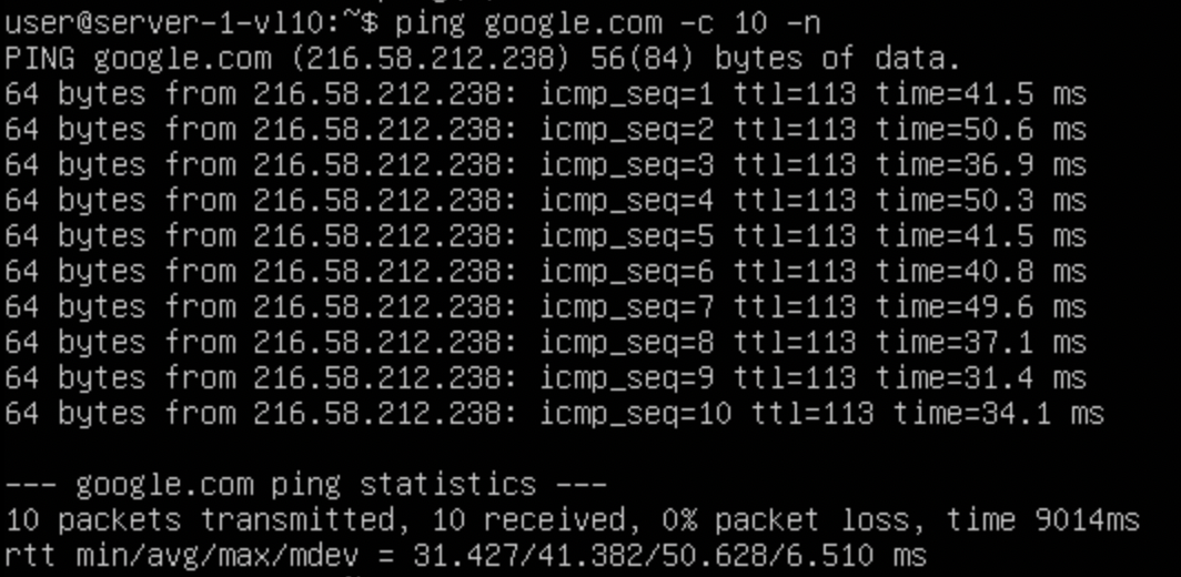
Great, we have internet access, we can see the logs on the firewall to:

Doing a traceroute, we can see that the traffic makes it to the firewall and then further beyond:
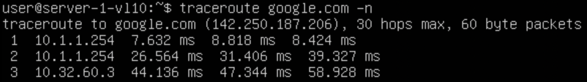
I've removed subsequent hops as it reveales Public IPs.
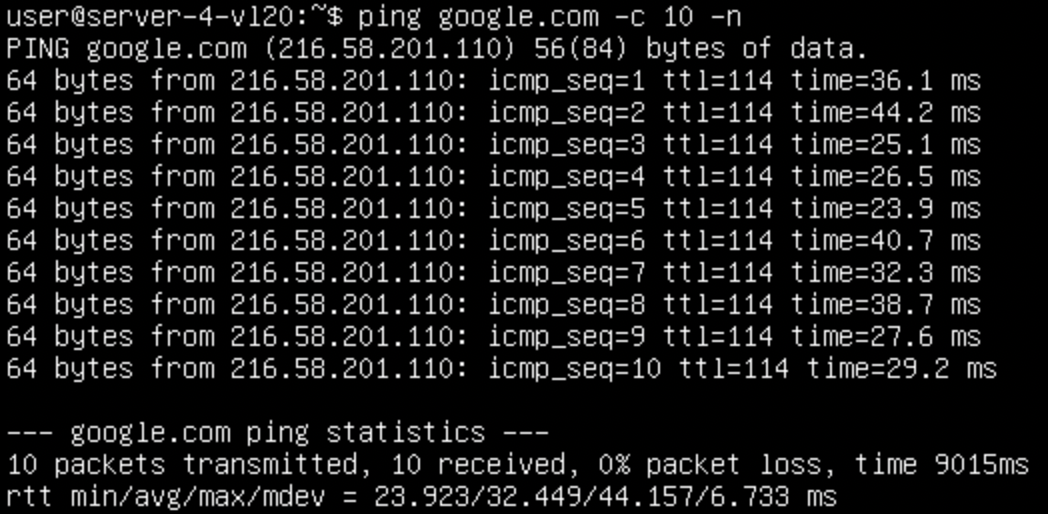
Lets also check from a vl20 server that it can reach the internet:
There is a caveat that we need to fix though, if we are trying to use this external connectivity from a host connected directly to a border leaf, and its local connection to the Firewall goes down, all the traffic gets blackholed. To resolve this, we need a peering between the two border leaves in order to transit the traffic between them.

0 Comments