In this guide, we are going to look at a less common, but still supported and deployed VXLAN EVPN model.
Lets say we have two (or more) Data Centres and we need to connect them at Layer 2, but we don't want to have a layer 2 link running between the DCs or we have an existing Layer 3 connection between them which we want to re-use. This is where this topology and design would come in.
For a new greenfield deployment, you would more commonly see two VXLAN EVPN Fabrics connected with Multi-Site which is a much more involved configuration. I do have a number of guides and videos on how to setup Multi-Site from scratch!
Topology and background information
This is the topology we are going to configure:

Its worth noting here that this design is L2 only. You could setup anycast gateways and tenant VRFs on the VTEPs if you wanted. However, the end goal here is to be able to communicate between the DCs at Layer 2. This design assumes the DCs already have an existing infrastructure for L3. A common use-case for this is something like vMotion or Live Migration that require a Layer 2 connection.
DC1-ACC and DC2-ACC are standard nexus switches, they do not have any VTEP configuration on them at all. Just a L2 VLAN and a port-channel connecting them up to the DCI switches. The DCI switches are acting as VTEPs in the topology. There are no spines, hence these sometimes being called 'Back to Back' VTEPs. Each DCs VTEPs are in a vPC Domain. This post assumes that you have the vPC already stood up and working. If you don't know what vPC is or how to set it up, I do have some guides on here about it, make a start here. We do want to make sure we use peer-switch under the vpc domain too as these switches are participating in Spanning Tree.
Underlay Routing and IP Addressing
In the underlay for the routing, we are going to use OSPF. This only applies to the DCI switches.
First off, we need loopbacks for all of the switches:
dc1-dci1: 10.0.0.1/32
dc1-dci2: 10.0.0.2/32
dc2-dci1: 10.0.0.3/32
dc2-dci2: 10.0.0.4/32
Lets enable OSPF and configure loopback0, remembering to change the IP for each VTEP:
feature ospf

interface Loopback0
  no shutdown
  ip address 10.0.0.x/32

router ospf UNDERLAY
  log-adjacency-changes

interface Loopback0
  ip router ospf UNDERLAY area 0.0.0.0
For the IP addressing in the interfaces in the underlay, between the DCs, we will use a pair of /30s and between switches in each DC we will use ip unnumbered because its nice and easy. Eth1/1 on each switch goes to the other DC and Eth1/2 is a L3 interconnect between the switches inside the DCs.
dc1-dci1:
interface Ethernet1/1
  no switchport
  mtu 9216
  medium p2p
  ip address 10.99.99.1/30
  ip router ospf UNDERLAY area 0.0.0.0
  no shutdown

interface Ethernet1/2
  no switchport
  mtu 9216
  medium p2p
  ip unnumbered loopback0
  ip router ospf UNDERLAY area 0.0.0.0
  no shutdown
dc1-dci2:
interface Ethernet1/1
  no switchport
  mtu 9216
  medium p2p
  ip address 10.100.100.1/30
  ip router ospf UNDERLAY area 0.0.0.0
  no shutdown

interface Ethernet1/2
  no switchport
  mtu 9216
  medium p2p
  ip unnumbered loopback0
  ip router ospf UNDERLAY area 0.0.0.0
  no shutdown
dc2-dci1:
interface Ethernet1/1
  no switchport
  mtu 9216
  medium p2p
  ip address 10.99.99.2/30
  ip router ospf UNDERLAY area 0.0.0.0
  no shutdown

interface Ethernet1/2
  no switchport
  mtu 9216
  medium p2p
  ip unnumbered loopback0
  ip router ospf UNDERLAY area 0.0.0.0
  no shutdown
dc2-dci2:
interface Ethernet1/1
  no switchport
  mtu 9216
  medium p2p
  ip address 10.100.100.2/30
  ip router ospf UNDERLAY area 0.0.0.0
  no shutdown

interface Ethernet1/2
  no switchport
  mtu 9216
  medium p2p
  ip unnumbered loopback0
  ip router ospf UNDERLAY area 0.0.0.0
  no shutdown
Multicast
In order to send BUM (Broadcast, Unknown Unicast and Multicast) traffic between the DCs, we can either use ingress replication, or Multicast. In this topology we are going to use Multicast Anycast RP where each of the DCI VTEPs are acting as an RP for resilience.
Its the exact same configuration on all the DCI switches:
feature pim

ip pim rp-address 10.0.0.99 group-list 224.0.0.0/4
ip pim ssm range 232.0.0.0/8
ip pim anycast-rp 10.0.0.99 10.0.0.1
ip pim anycast-rp 10.0.0.99 10.0.0.2
ip pim anycast-rp 10.0.0.99 10.0.0.3
ip pim anycast-rp 10.0.0.99 10.0.0.4

interface loopback1
  ip address 10.0.0.99/32
  ip router ospf UNDERLAY area 0.0.0.0
  ip pim sparse-mode

interface loopback0
  ip pim sparse-mode

int eth1/1-2
  ip pim sparse-mode
There is no configuration required on the ACC switches for Multicast.
We can verify the RP configuration on a VTEP:
dc2-dci1# show ip pim rp
PIM RP Status Information for VRF "default"
BSR disabled
Auto-RP disabled
BSR RP Candidate policy: None
BSR RP policy: None
Auto-RP Announce policy: None
Auto-RP Discovery policy: None

Anycast-RP 10.0.0.99 members:
  10.0.0.1  10.0.0.2  10.0.0.3*  10.0.0.4

RP: 10.0.0.99*, (0),
 uptime: 02:28:56   priority: 255,
 RP-source: (local),
 group ranges:
 224.0.0.0/4
NVE Configuration
Now we need to setup the VTEP (NVE) interface on each of the DCI switches. Firstly, we need to create another loopback (loopback2) to source this from.
Due to this being a vPC enabled environment, there is a secondary Anycast VTEP address added to the interface which is the same on each vPC domain:
dc1-dci1: 10.0.1.1/32
dc1-dci2: 10.0.1.2/32
dc2-dci1: 10.0.1.3/32
dc2-dci2: 10.0.1.4/32
And then each vPC pair needs a secondary IP address on the loopback2 interface which is common:
vpc domain 100 (dc1): 10.0.1.101/32
vpc domain 200 (dc2): 10.0.1.102/32
For example on dc1-dci1:
interface loopback2
  ip address 10.0.1.1/32
  ip address 10.0.1.101/32 secondary
  ip router ospf UNDERLAY area 0.0.0.0
  ip pim sparse-mode
and dc1-dci2:
interface loopback2
  ip address 10.0.1.2/32
  ip address 10.0.1.101/32 secondary
  ip router ospf UNDERLAY area 0.0.0.0
  ip pim sparse-mode
The NVE Interface configuration for all DCI switches:
feature fabric forwarding
feature vn-segment-vlan-based
feature nv overlay

interface nve1
  no shutdown
  host-reachability protocol bgp
  advertise virtual-rmac
  source-interface loopback2
advertise virtual-rmac is another vPC specific command to advertise the virtual mac for the vPC Pair.
BGP Overlay Routing
For the overlay routing and for transmission of type-2 EVPN routes, we use BGP. There are no route reflectors in this topology, so we will have a full mesh of peerings, which is only 3 per switch, so its not that bad to manage.
This is the configuration for dc1-dci1:
feature bgp

router bgp 64500
  log-neighbor-changes
  address-family ipv4 unicast
  address-family l2vpn evpn
    advertise-pip
  template peer VTEP
    remote-as 64500
    update-source loopback0
    address-family ipv4 unicast
      send-community extended
      soft-reconfiguration inbound
    address-family l2vpn evpn
      send-community
      send-community extended
  neighbor 10.0.0.2
    inherit peer VTEP
  neighbor 10.0.0.3
    inherit peer VTEP
  neighbor 10.0.0.4
    inherit peer VTEP
On the other DCI switches, we just need to swap the neighbors. For example, dc2-dci1 will have 10.0.0.1, 10.0.0.2 and 10.0.0.4. In order to form a mesh of connections:
dc1-dci1# show bgp l2vpn evpn summary
BGP summary information for VRF default, address family L2VPN EVPN
BGP router identifier 10.0.0.1, local AS number 64500
BGP table version is 22, L2VPN EVPN config peers 3, capable peers 3
0 network entries and 0 paths using 0 bytes of memory
BGP attribute entries [0/0], BGP AS path entries [0/0]
BGP community entries [0/0], BGP clusterlist entries [0/0]

Neighbor        V    AS    MsgRcvd    MsgSent   TblVer  InQ OutQ Up/Down  State/PfxRcd
10.0.0.2        4 64500        170        170        0    0    0 00:00:05 0
10.0.0.3        4 64500        171        166        0    0    0 00:00:05 0
10.0.0.4        4 64500        168        166        0    0    0 00:00:04 0

Neighbor        T    AS PfxRcd     Type-2     Type-3     Type-4     Type-5
10.0.0.2        I 64500 0          0          0          0          0
10.0.0.3        I 64500 0          0          0          0          0
10.0.0.4        I 64500 0          0          0          0          0
L2VNI Configuration
Last thing we need to do is create the Vlan and all the VNI mappings for it. Again, this config is just for the DCI switches:
vlan 100
  vn-segment 100100

interface nve1
  member vni 100100
    mcast-group 224.1.1.192

evpn
  vni 100100 l2
    rd auto
    route-target import auto
    route-target export auto
Verification
And with that, the VTEPs are configured. From each VTEP we have port-channel2 which goes to the ACC switch in each DC:
interface port-channel2
  switchport mode trunk
  vpc 2
This hs just a standard L2 trunk as the ACC switches have no knowledge of VXLAN or any fabric services. They just have access ports connected to the end hosts:
interface Ethernet1/3
  switchport access vlan 100
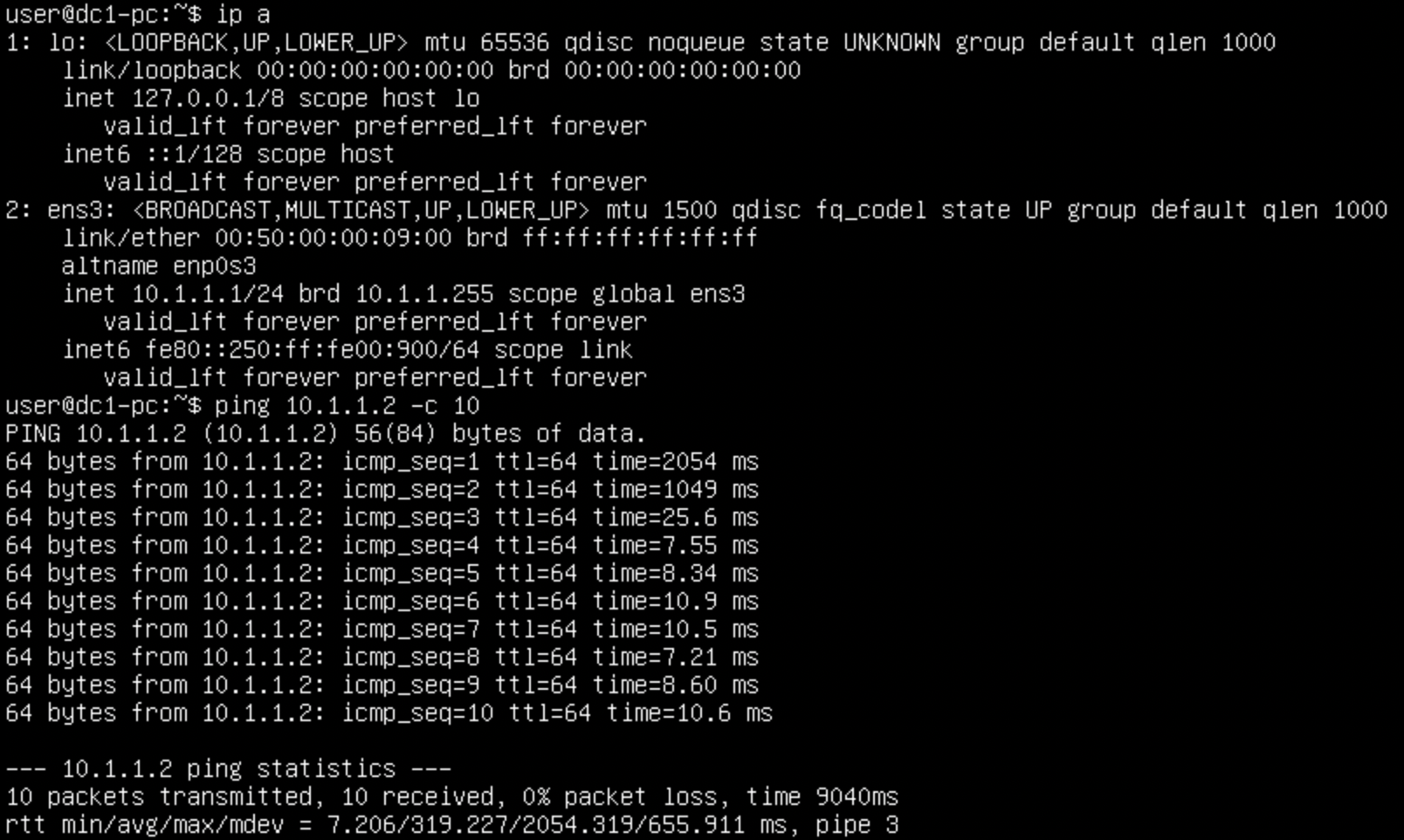
From the perspective of the hosts, lets see if they can ping one another:

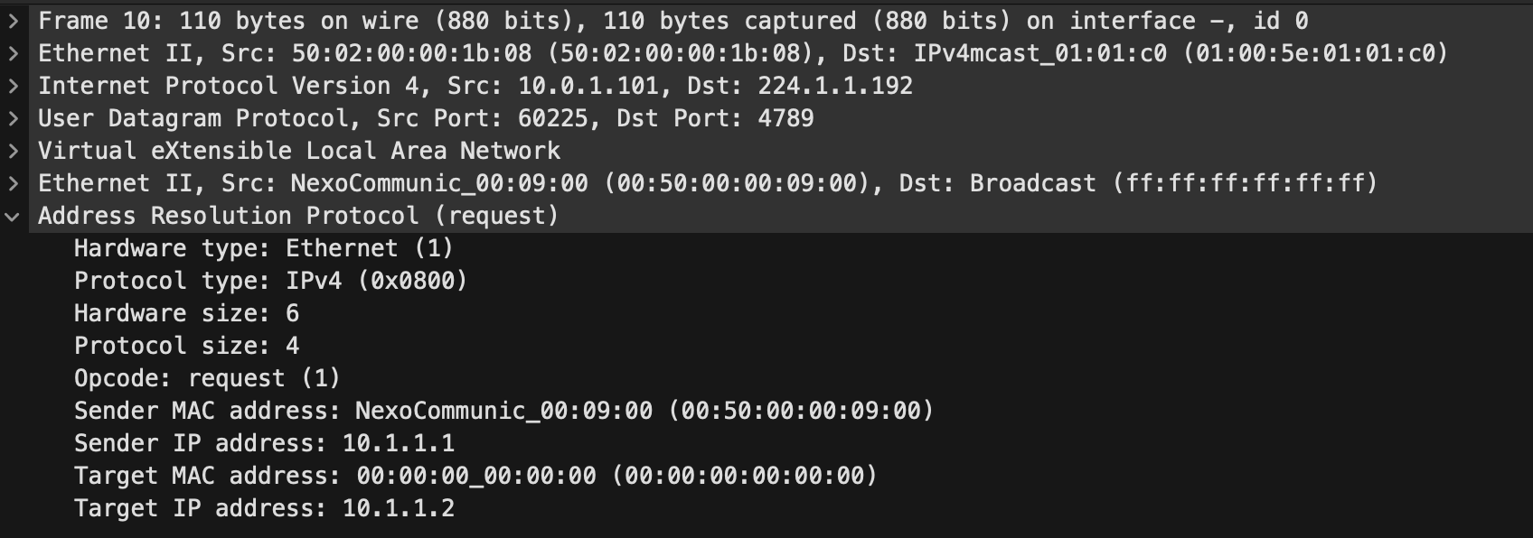
Perfect, the first ping took a bit longer, this was because of ARP having to transit over the DCI links. Which we can see if we do a capture:

The IP destination of this was 224.1.1.192 which we know is the multicast group for the L2VNI.
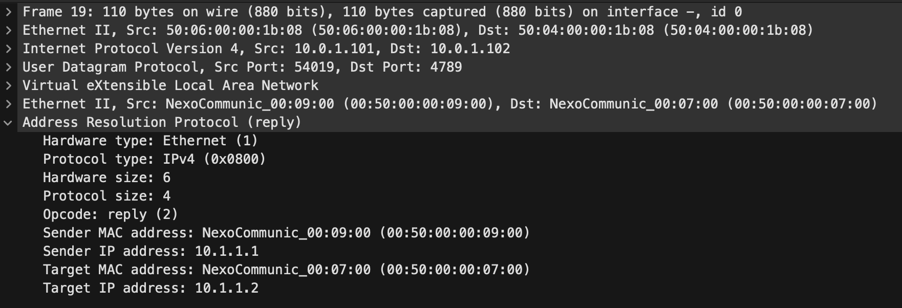
And we see the reply come as a direct unicast now the VTEPs are known:

We can also check the l2route tables and check we have entries in there for the local and remote endpoints:
dc1-dci1# show l2route evpn mac evi 100 detail

Flags -(Rmac):Router MAC (Stt):Static (L):Local (R):Remote
(Dup):Duplicate (Spl):Split (Rcv):Recv (AD):Auto-Delete (D):Del Pending
(S):Stale (C):Clear, (Ps):Peer Sync (O):Re-Originated (Nho):NH-Override
(Asy):Asymmetric (Gw):Gateway
(Bh):Blackhole
(Pf):Permanently-Frozen, (Orp): Orphan

(PipOrp): Directly connected Orphan to PIP based vPC BGW
(PipPeerOrp): Orphan connected to peer of PIP based vPC BGW
Topology    Mac Address    Prod   Flags              Seq No     Next-Hops
----------- -------------- ------ ------------------- ---------- ---------------------------------------------------------
100         0050.0000.0700 BGP    Rcv                0          10.0.1.102 (Label: 100100)
            Route Resolution Type: Regular
            Forwarding State: Resolved (PeerID: 1)
            Sent To: L2FM
            SOO: 808333361
            Encap: 1

100         0050.0000.0900 Local  L,                 0          Po2
            Route Resolution Type: Regular
            Forwarding State: Resolved
            Sent To: BGP
            SOO: 808333361
That looks good! We don't see IP addresses in this topology because we don't have any Layer3 services on the VTEPs like anycast gateways. We also are not able to make use of arp suppression here either as Cisco don't support it without Layer3 services.
Last but not least, we can check multicast to make sure that looks good:
dc1-dci1# show ip pim neighbor
PIM Neighbor Status for VRF "default"
Neighbor        Interface            Uptime    Expires   DR       Bidir-  BFD    ECMP Redirect
                                                         Priority Capable State     Capable
10.99.99.2      Ethernet1/1          02:51:38  00:01:22  1        yes     n/a     no
10.0.0.2        Ethernet1/2          02:50:45  00:01:43  1        yes     n/a     no
dc1-dci1# show ip mroute
IP Multicast Routing Table for VRF "default"

(*, 224.1.1.192/32), uptime: 02:53:41, nve ip pim
  Incoming interface: loopback1, RPF nbr: 10.0.0.99
  Outgoing interface list: (count: 1)
    nve1, uptime: 02:53:41, nve

(10.0.1.101/32, 224.1.1.192/32), uptime: 02:53:41, nve mrib ip pim
  Incoming interface: loopback2, RPF nbr: 10.0.1.101, internal
  Outgoing interface list: (count: 1)
    Ethernet1/1, uptime: 02:47:33, pim

(10.0.1.102/32, 224.1.1.192/32), uptime: 02:46:20, pim mrib ip
  Incoming interface: Ethernet1/1, RPF nbr: 10.99.99.2, internal
  Outgoing interface list: (count: 1)
    nve1, uptime: 02:46:20, mrib

(*, 232.0.0.0/8), uptime: 02:53:42, pim ip
  Incoming interface: Null, RPF nbr: 0.0.0.0
  Outgoing interface list: (count: 0)
From that output, we can see that this VTEP has registered two (S,G) entries for its own VTEP IP and the IP of the remote VTEP. The outgoing interfaces tell us where frames will be forwarded if they come in and match the criteria. We also see a couple of neighbors for pim which is the local DCI switch and the directly connected inter-dc switch.
Finally, its worth mentioning about failover. In a leaf and spine architecture, its not common to have a Layer 3 link between the switches. You may have one for the peer-keepalive, but not like we have in this topology with Eth1/2. Normally, when configuring vPC VXLAN, you need to setup a backup peering in the underlay and use nve infra-vlans. However, when you have a dedicated Layer3 link like we do in this topology, this is no required because we are not using an SVI or the peer-link to form a neighborship. Eth1/2 is a direct connection separate from the vPC setup. Due to this, we also don't require the layer3 peer-router command under the vPC domain.
Thats it for this setup, nice and easy!
Accompanying YouTube video:
Full configurations:


0 Comments