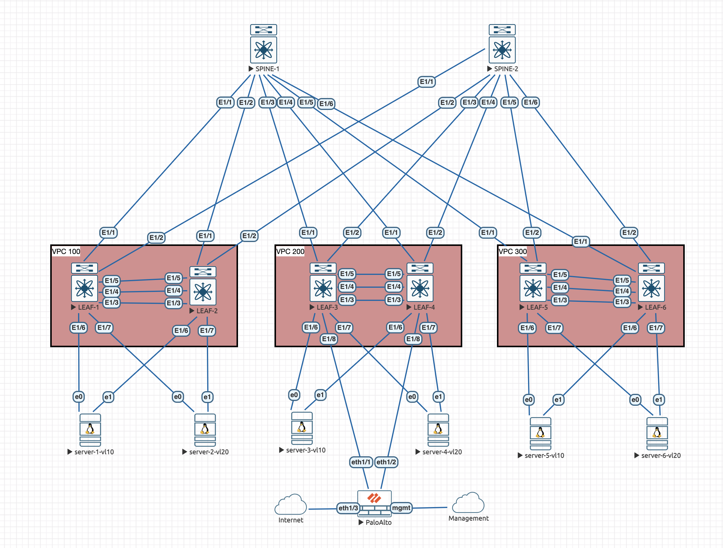
So, now we have external connectivity fully working, lets have a look at a failure scenario and how we can put some config in to resolve.
Lets take a look at the topology:

The issue
In the event that a leaf looses all its uplinks to the spines, or a vPC orphan port connected to a single switch has traffic destined for it, sent to the other vPC switch. In both of these scenarios, the vPC peer-link would be required in order to shuttle the traffic between the switches.
Either of these scenarios are solved by infra vlans, so ill simulate the uplinks failing to a leaf..
Lets say that LEAF-1 looses all its uplinks to the spines. Traffic coming from server-1-vl10 will use its hashing algorithm in order to choose which local interface to send the traffic from. In the event it chose to send the traffic upstream to LEAF-1, we would have a problem.
Lets check the state of LEAF-1 now its lost its uplinks:
LEAF-1# show ip route vrf all

10.0.0.3/32, ubest/mbest: 2/0, attached
    *via 10.0.0.3, Lo0, [0/0], 00:12:12, local
    *via 10.0.0.3, Lo0, [0/0], 00:12:12, direct
10.0.1.1/32, ubest/mbest: 2/0, attached
    *via 10.0.1.1, Lo1, [0/0], 00:05:41, local
    *via 10.0.1.1, Lo1, [0/0], 00:05:41, direct
10.0.1.101/32, ubest/mbest: 2/0, attached
    *via 10.0.1.101, Lo1, [0/0], 00:05:41, local
    *via 10.0.1.101, Lo1, [0/0], 00:05:41, direct

IP Route Table for VRF "OVERLAY-TENANT1"

10.1.1.0/24, ubest/mbest: 1/0, attached
    *via 10.1.1.254, Vlan10, [0/0], 00:08:32, direct
10.1.1.1/32, ubest/mbest: 1/0, attached
    *via 10.1.1.1, Vlan10, [190/0], 00:03:33, hmm
10.1.1.254/32, ubest/mbest: 1/0, attached
    *via 10.1.1.254, Vlan10, [0/0], 00:08:32, local

IP Route Table for VRF "OVERLAY-TENANT2"

10.2.1.0/24, ubest/mbest: 1/0, attached
    *via 10.2.1.254, Vlan20, [0/0], 00:08:32, direct
10.2.1.254/32, ubest/mbest: 1/0, attached
    *via 10.2.1.254, Vlan20, [0/0], 00:08:32, local

LEAF-1# show bgp l2vpn evpn summary | beg Neighbor
Neighbor        V    AS    MsgRcvd    MsgSent   TblVer  InQ OutQ Up/Down  State/PfxRcd
10.0.0.1        4 64500         72         13        0    0    0 00:01:14 Idle
10.0.0.2        4 64500         72         13        0    0    0 00:01:14 Idle

Neighbor        T    AS PfxRcd     Type-2     Type-3     Type-4     Type-5
10.0.0.1        I 64500 Idle       0          0          0          0
10.0.0.2        I 64500 Idle       0          0          0          0
As we can see, theres not much of anything in the routing tables and the BGP peerings to the spines are down. So no VXLAN traffic is going to leave this switch, its just going to be dropped.
We can show this by trying to do a ping from server-1-vl10:

Thats not doing much of anything! So lets fix it!
Resolution
In order to resolve this, we need to get LEAF-1 back into the igp in order for it to be able to re-establish peerings with the fabric.
Its worth noting that this config is required on each set of VPC domain switches. We need to ensure we use a different subnet on each set of switches though.
This is the example config:
vlan 900
exit

interface Vlan900
  no shutdown
  no ip redirects
  ip address x.x.x.x/30
  ip ospf network point-to-point
  ip router ospf UNDERLAY area 0.0.0.0

system nve infra-vlans 900
In my case, I will use the following IPs:
-
LEAF-1 - 10.0.3.1/30
-
LEAF-2 - 10.0.3.2/30
-
LEAF-3 - 10.0.3.5/30
-
LEAF-4 - 10.0.3.6/30
-
LEAF-5 - 10.0.3.9/30
-
LEAF-6 - 10.0.3.10/30
Verification
We should be able to see a single OSPF neighbor has come up on LEAF-1 now:
LEAF-1# show ip ospf UNDERLAY neighbors
 OSPF Process ID UNDERLAY VRF default
 Total number of neighbors: 1
 Neighbor ID     Pri State            Up Time  Address         Interface
 10.0.0.4          1 FULL/ -          00:02:49 10.0.3.2        Vlan900
Thats a good sign, we should now have a lot more routes, and more importantly, we should have the l2vpn evpn BGP peerings back with the spines:
LEAF-1# show bgp l2vpn evpn summary | beg Neighbor
Neighbor        V    AS    MsgRcvd    MsgSent   TblVer  InQ OutQ Up/Down  State/PfxRcd
10.0.0.1        4 64500        142         21      421    0    0 00:03:18 50
10.0.0.2        4 64500        141         20      421    0    0 00:02:20 50

Neighbor        T    AS PfxRcd     Type-2     Type-3     Type-4     Type-5
10.0.0.1        I 64500 50         24         0          0          26
10.0.0.2        I 64500 50         24         0          0          26
The route for the spines should be via Vlan900
LEAF-1# show ip route 10.0.0.1
IP Route Table for VRF "default"

10.0.0.1/32, ubest/mbest: 1/0
    *via 10.0.3.2, Vlan900, [110/81], 00:04:25, ospf-UNDERLAY, intra
If we jump back to server-1-vl10 which was previously not able to communicate with any endpoints in the fabric, we can see that it now can:

Once the infra-vlan peering is setup on all of the leaves, this should cover the failure scenario here. When the uplinks come back up, the peerings should come back up directly and switch back to using the shortest path!

0 Comments