This guide marks the first of a few guides related to Cisco Nexus vPC. Standing for Virtual Port-Channel. This is very much like the well-loved Stackwise concept for Catalyst switches. However, instead of the devices becoming a single logical switch with one management plane, the devices stay individually managed. vPC lets you run port-channels from the pair of switches though and downstream devices don't know the difference.
This is a cool technology. However, it has a lot of knobs and dials that need to be considered to ensure that you have a hassle free implementation of vPC.
In this guide, we are going to run through some of the theory concepts and then setup a quick and simple vPC pair.
Requirements
vPC only works on Cisco Nexus Switches, no other Cisco devices support this technology.
vPC requires physical links between the switches from the normal "front panel" ports. Rather than dedicated ports like stackwise uses.
Concepts
Peer Link
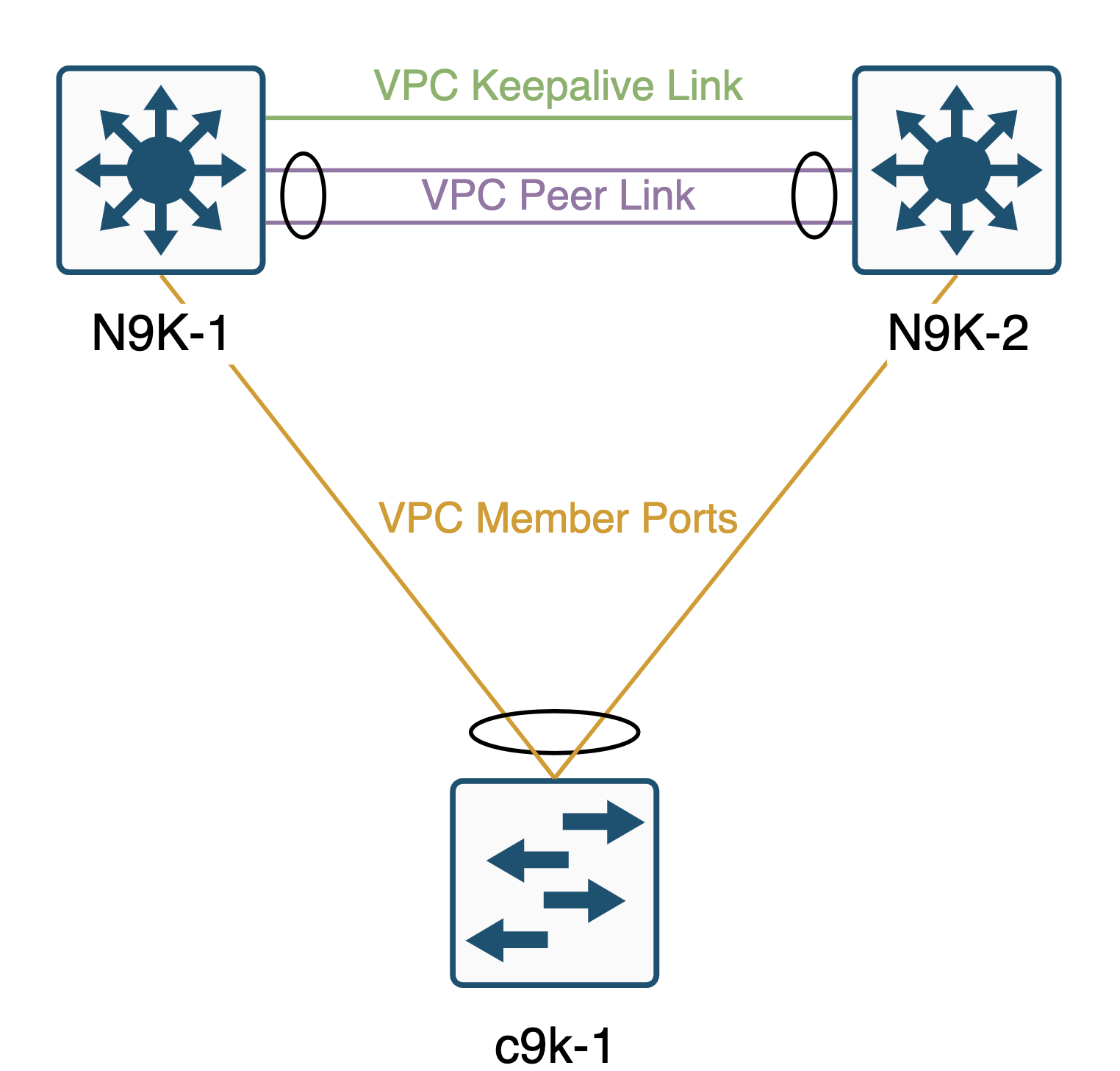
One of the required links between the switches is whats called the vPC Peer link. Cisco recommend that this is at least 2 x 10GE interfaces. If you are using a chassis switch, they also recommend having the interfaces on different linecards, but thats not always possible if you have a fixed Nexus switch. All interfaces you use for the vPC peer link will be part of a port-channel to aggregate the links.
Under the hood, the vPC Peer link is just a Layer 2 trunk between the two switches, its used for shuttling traffic between the switches based on the mac-address table like any trunk link would. However, it also has CFS (Cisco Fabric Services) traffic going over it, which is critical to the functionality of vPC. No Peer link means no vPC in effect. This link should be very well guarded with protocols like UDLD for example. Cisco also recommends using the STL type 'Network' on the vPC peer link too.
Keepalive Link
Another requirement of vPC is whats called a Peer Keepalive link. There are a couple of main options for the keepalive link and one is better than the other. The most preferred method is to have an L3 interface (or L3 port-channel) between the switches in a dedicated VRF. The other option is to use the mgmt0 interfaces to run the keepalive between the management interfaces, this is still a viable option, its just not the best option as it brings other switches into scope as its unlikely you have your mgmt0 interfaces connected physically!
The purpose of the Keepalive Link is to determine the status of the peer switch. It is used to determine if a peer link failure is a failure of the link or a failure of the peer device. If the links and the keepalive go down, its a safe bet its the device rebooting etc, if the peer link goes down but the keepalive stays up, you may have had a cabling or dataplane fault.
Its a very good idea to keep the peer link and keepalive links separated. Its not acceptable to run the vPC peer keepalive on SVIs using the Peer Link for transit. Unless you like having to deal with split-brain scenarios!
vPC Domain
The vPC domain is an ID between 1 and 1000 that identifies the peer connection between the two switches. This needs to match between the switches.
Example
Here is an example of two vPC peer switches with a downstream catalyst switch:

Configuration
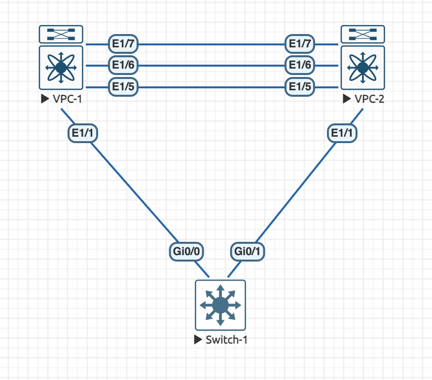
Now that we have looked at the concepts for vPC, lets configure it on a pair of Nexus 9K Switches. Here is our topology:

On both of the Nexus switches, we first need to enable the feature for vPC, this is common with Nexus platforms:
feature vpcWe are going to use Eth1/5 for the peer keepalive link and then Eth1/6 and Eth1/7 for the peer link.
Lets configure the keepalive link, we need to create a VRF for this to live in on each Nexus:
vrf context VPC_KEEPALIVE
exit
And configure each interface, giving each switch an different IP:
interface Ethernet1/5
  no switchport
  vrf member VPC_KEEPALIVE
  ip address 172.16.0.x/30
  no shutdown
In this example, I have configured VPC-1 as 172.16.0.1 and VPC-2 as 172.16.0.2. We should now be able to ping between the switches:
VPC-1# ping 172.16.0.1 vrf VPC_KEEPALIVE
PING 172.16.0.1 (172.16.0.1): 56 data bytes
64 bytes from 172.16.0.1: icmp_seq=0 ttl=255 time=13.886 ms
64 bytes from 172.16.0.1: icmp_seq=1 ttl=255 time=0.381 ms
64 bytes from 172.16.0.1: icmp_seq=2 ttl=255 time=0.343 ms
64 bytes from 172.16.0.1: icmp_seq=3 ttl=255 time=0.275 ms
64 bytes from 172.16.0.1: icmp_seq=4 ttl=255 time=0.264 ms

--- 172.16.0.1 ping statistics ---
5 packets transmitted, 5 packets received, 0.00% packet loss
round-trip min/avg/max = 0.264/3.029/13.886 ms
Before we can move onto the peer link, we need to initiate the vPC domain on both Nexus switches and configure the keepalives:
VPC-1:
vpc domain 100
  peer-keepalive destination 172.16.0.2 source 172.16.0.1 vrf VPC_KEEPALIVE
exit
VPC-2:
vpc domain 100
  peer-keepalive destination 172.16.0.1 source 172.16.0.2 vrf VPC_KEEPALIVE
exit
Here we are telling the switches that they are operating in vPC domain 100 and to use the dedicated links for the keepalive with the source being its own local IP and the destination being the IP of the other switch, nice and simple!
Now we can configure the peer link interfaces:
feature lacp
interface Eth1/6-7
  channel-group 1 mode active
  no shutdown
interface port-channel1
  switchport mode trunk
  spanning-tree port type network
  vpc peer-link
If we use the show vpc brief command we should see that the vPC peering has formed:
VPC-1# show vpc brief
Legend:
                (*) - local vPC is down, forwarding via vPC peer-link

vPC domain id                     : 100
Peer status                       : peer adjacency formed ok
vPC keep-alive status             : peer is alive
Configuration consistency status  : success
Per-vlan consistency status       : success
Type-2 consistency status         : success
vPC role                          : primary
Number of vPCs configured         : 0
Peer Gateway                      : Disabled
Dual-active excluded VLANs        : -
Graceful Consistency Check        : Enabled
Auto-recovery status              : Disabled
Delay-restore status              : Timer is off.(timeout = 30s)
Delay-restore SVI status          : Timer is off.(timeout = 10s)
Delay-restore Orphan-port status  : Timer is off.(timeout = 0s)
Operational Layer3 Peer-router    : Disabled
Virtual-peerlink mode             : Disabled

vPC Peer-link status
---------------------------------------------------------------------
id    Port   Status Active vlans
--    ----   ------ -------------------------------------------------
1     Po1    up     1
We can see that the peer adjacency has formed and that the keepalive is working as Switch 1 can see switch 2. The same output would be expected on the other switch. We can also see here that the role of this switch is primary. That will be important later when we talk about failure scenarios.
Now the switches are configured for vPC, we can create one and link up the switch that is connected downstream.
This configuration is for both Nexus switches, when creating vPCs, the IDs you assign must match, though the port-channel number is still local, it does make sense to match them though!
interface Ethernet1/1
  channel-group 2 mode active
  no shutdown
interface port-channel2
  switchport mode trunk
  vpc 2
Then we need to remember to configure the downstream switch:
interface range g0/0-1
  channel-group 1 mode active
interface port-channel1
  switchport mode trunk
The catalyst switch requires no special commands, it knows nothing about vPC, its just a standard LACP port channel.
We can confirm that by checking the status on the downstream switch:
Switch-1#show etherchannel summary
Flags:  D - down        P - bundled in port-channel
        I - stand-alone s - suspended
        H - Hot-standby (LACP only)
        R - Layer3      S - Layer2
        U - in use      N - not in use, no aggregation
        f - failed to allocate aggregator

        M - not in use, minimum links not met
        m - not in use, port not aggregated due to minimum links not met
        u - unsuitable for bundling
        w - waiting to be aggregated
        d - default port

        A - formed by Auto LAG

Number of channel-groups in use: 1
Number of aggregators:           1

Group  Port-channel  Protocol    Ports
------+-------------+-----------+-----------------------------------------------
1      Po1(SU)         LACP      Gi0/0(P)    Gi0/1(P)
Both interfaces are bundled.
And on the Nexus switches, there are a couple of commands we can use for verification.
This shows the local port-channel configuration and status:
VPC-1# show port-channel summary interface port-channel 2
Flags:  D - Down        P - Up in port-channel (members)
        I - Individual  H - Hot-standby (LACP only)
        s - Suspended   r - Module-removed
        b - BFD Session Wait
        S - Switched    R - Routed
        U - Up (port-channel)
        p - Up in delay-lacp mode (member)
        M - Not in use. Min-links not met
--------------------------------------------------------------------------------
Group Port-       Type     Protocol  Member Ports
      Channel
--------------------------------------------------------------------------------
2     Po2(SU)     Eth      LACP      Eth1/1(P)
And we can use this to check the vPC side of things:
VPC-1# show vpc 2

vPC status
----------------------------------------------------------------------------
Id    Port          Status Consistency Reason                Active vlans
--    ------------  ------ ----------- ------                ---------------
2     Po2           up     success     success               1
If we add a client to the switch, we will see the mac addresses appear on the vPC switches:
VPC-1# show mac address-table int po2
Legend:
        * - primary entry, G - Gateway MAC, (R) - Routed MAC, O - Overlay MAC
        age - seconds since last seen,+ - primary entry using vPC Peer-Link,
        (T) - True, (F) - False, C - ControlPlane MAC, ~ - vsan,
        (NA)- Not Applicable
   VLAN     MAC Address      Type      age     Secure NTFY Ports
---------+-----------------+--------+---------+------+----+------------------
*    1     0050.7966.6806   dynamic  NA         F      F    Po2
VPC-2# show mac address-table int po2
Legend:
* - primary entry, G - Gateway MAC, (R) - Routed MAC, O - Overlay MAC
age - seconds since last seen,+ - primary entry using vPC Peer-Link,
(T) - True, (F) - False, C - ControlPlane MAC, ~ - vsan,
(NA)- Not Applicable
VLAN MAC Address Type age Secure NTFY Ports
---------+-----------------+--------+---------+------+----+------------------
+ 1 0050.7966.6806 dynamic NA F F Po2This proves we are seeing the client via the port channel and thus concludes the basic setup of a vPC. There are of course, lots of different configurations for the vPC domain that we can use to accommodate for specific events and configuration existing. We wil go through those in the next sections.

2 Comments
Jason · 11th September 2025 at 4:26 pm
Nick,
Thanks very much for this. I swear this is an order of operation pitfall. I had all the correct configs entered on my downstream Nexus pair and the upstream switch, but one of the links kept showing as suspended whenever I tried to bring up the Port-Channel. Your step by step was the correct way to do it and my vPC came up with both members up and bundled after that. So used to define and assign, but in this case it is assign the port channel to the interfaces BEFORE actually creating and defining the port-channel.
Nick Carlton · 25th October 2025 at 10:00 pm
Hi Jason,
NX-OS is sometimes a bit funny about order of operations. However, when you assign the first interface to a Port-Channel, if it doesnt already exist it will create it. If you inspect the running/startup config, you will actually see the Port-Channel interface definitions before the Physical Interfaces.
I find when this happens sometimes, I need to remove the port-channel and let the switch re-create it. Ive seen it on a few different NX-OS versions, mainly older 9.x versions.
Thanks
Nick